Question Help troubleshooting bad video output

Joined
Mar 26, 2023
Messages
12
Likes
4
I am working on an Ashida and have a trimmed wii that I plugged in to test and got bad video that doesn’t match anything I’ve seen elsewhere, so I’m hoping someone can tell me what I’ve done wrong.

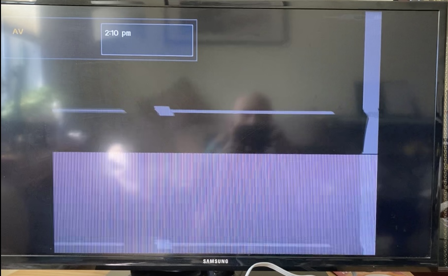
After pressing the power button, the wii turns on and outputs some garbled video, shown below. The screen scrolls and the snow flickers in and out before the wii resets itself after 5-8 seconds.

DA79BB1C-7A29-444E-A1F1-439AB9C0A4D8.jpeg

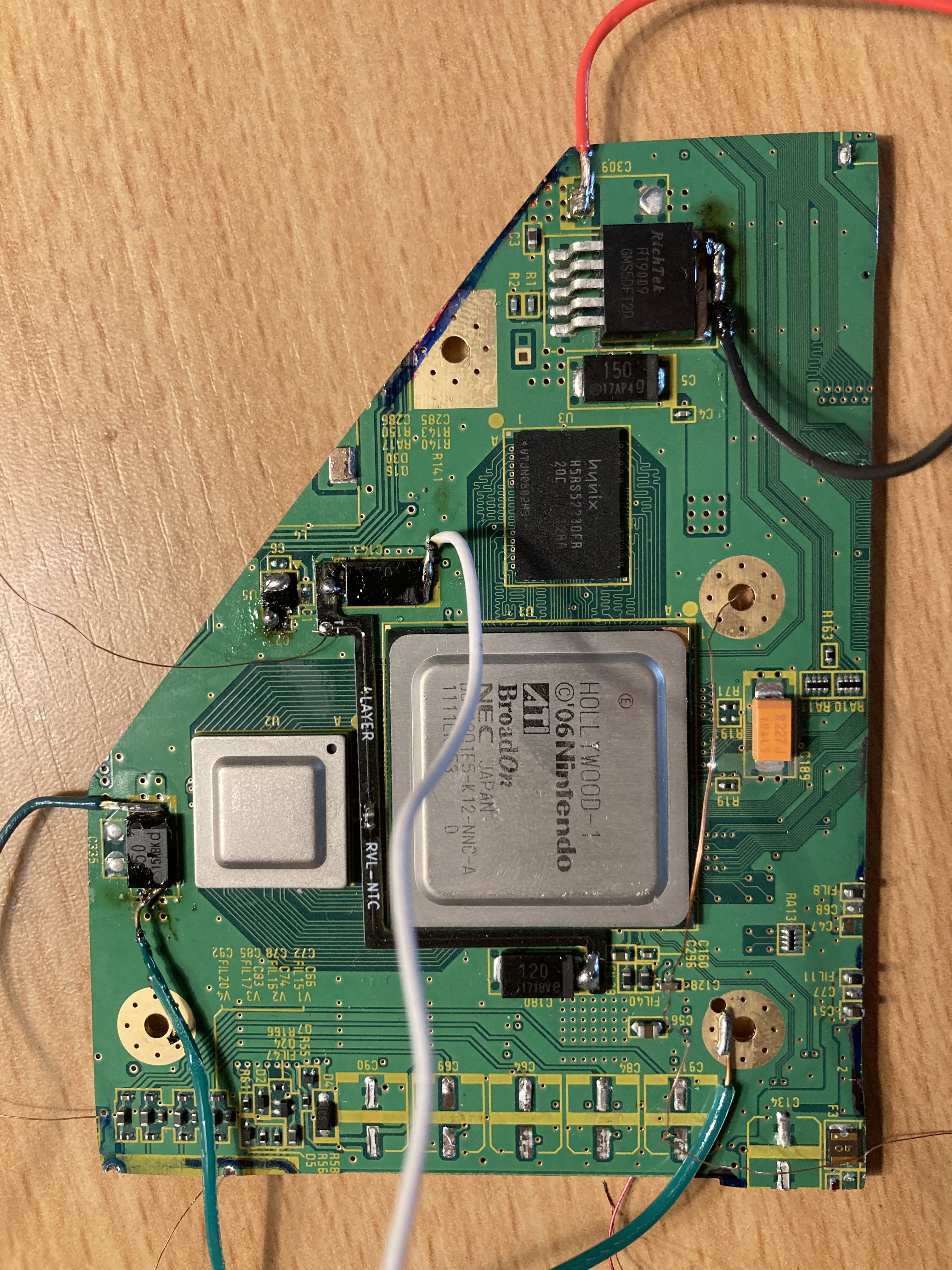
I have installed RVLoader, patched out WiFi, and checked resistances on the board. One thing I did mess up is I tried to relocate U10 instead of just using the PMS-lite output, but get the same video output whether I use my (poorly) relocated U10 or the PMS-lite U10 connection.

Below is a picture of the board with my awful solder work.
F48A8E46-97A0-40A5-A369-5E42C33704E2.jpeg


Thanks for any help/suggestions!
 
Joined
Mar 26, 2023
Messages
12
Likes
4
8463B9F1-3158-49D9-8E47-BCE03D26CE55.jpeg

I have already connected wires to the SCW/SDW vias but they are not connected to anything on the other end.
 
Joined
Mar 26, 2023
Messages
12
Likes
4
That was my first attempt soldering to a via so I taped it down the moment it seemed to hold, but I see what you’re saying. I’ll redo it and report back.
 

Stitches

2 and a Half Dollarydoos
Staff member
.
.
Joined
Feb 5, 2017
Messages
3,817
Likes
3,011
Location
Banana Bender Land, Australia
Portables
6
I would also ditch that jacketed solid core wire you're using for the voltage connections and replace it with 22AWG stranded wire. Using solid core for voltage supply is very much not recommended
 
Joined
Mar 26, 2023
Messages
12
Likes
4
I would also ditch that jacketed solid core wire you're using for the voltage connections and replace it with 22AWG stranded wire. Using solid core for voltage supply is very much not recommended
Thanks, I had actually initially started trying with the solid core i had on hand and have since switched to 22AWG stranded; the only solid wire I did not swap is the ground (light green). Everything else is stranded 22 gauge and I intend to switch the grounds out, too (just didn’t get there for the test run).
 

Stitches

2 and a Half Dollarydoos
Staff member
.
.
Joined
Feb 5, 2017
Messages
3,817
Likes
3,011
Location
Banana Bender Land, Australia
Portables
6
Thanks, I had actually initially started trying with the solid core i had on hand and have since switched to 22AWG stranded; the only solid wire I did not swap is the ground (light green). Everything else is stranded 22 gauge and I intend to switch the grounds out, too (just didn’t get there for the test run).
Funnily enough, the ground connection is the most important wire to not be using the wrong type of. Swapping it over probably won't fix all the issues, but it will at least narrow it down.

I also noticed that your u10 is blobbed as fuck. I'd clean that up a bit and ensure the 3.3v input leg is properly secured to the board. In your photos it looks a bit like it's floating
 

Viilmo

.
Joined
Jun 23, 2021
Messages
208
Likes
92
Location
Germany
Portables
1
Also a tip: When removing the caps dont desolder them but rather twist them. It puts less force on them and reduces the chance of ripping them like they look in the picture.
 
Joined
Mar 26, 2023
Messages
12
Likes
4
Funnily enough, the ground connection is the most important wire to not be using the wrong type of. Swapping it over probably won't fix all the issues, but it will at least narrow it down.

I also noticed that your u10 is blobbed as fuck. I'd clean that up a bit and ensure the 3.3v input leg is properly secured to the board. In your photos it looks a bit like it's floating
Switching the solid wire to stranded (and/or cleaning up those joints) and cleaning up the 3.3 line did seem to make a difference; the picture isn’t stable but I could sort of make out the text I expect to appear.

I guess my next step might just be trying to redo everything more cleanly. Could the U5 chip area be causing me problems?

Also a tip: When removing the caps dont desolder them but rather twist them. It puts less force on them and reduces the chance of ripping them like they look in the picture.
Thanks for that tip - I did get a backup Wii in case I let the smoke out of this one (or need another portable).
 

Stitches

2 and a Half Dollarydoos
Staff member
.
.
Joined
Feb 5, 2017
Messages
3,817
Likes
3,011
Location
Banana Bender Land, Australia
Portables
6
Switching the solid wire to stranded (and/or cleaning up those joints) and cleaning up the 3.3 line did seem to make a difference; the picture isn’t stable but I could sort of make out the text I expect to appear.


Switching the solid wire to stranded (and/or cleaning up those joints) and cleaning up the 3.3 line did seem to make a difference; the picture isn’t stable but I could sort of make out the text I expect to appear.

I guess my next step might just be trying to redo everything more cleanly. Could the U5 chip area be causing me problems?


Thanks for that tip - I did get a backup Wii in case I let the smoke out of this one (or need another portable).
I would redo the u10 relocation, yeah. Just to be sure
 
Joined
Mar 26, 2023
Messages
12
Likes
4
I would redo the u10 relocation, yeah. Just to be sure
Edit: I apparently can’t read. I will do that, too, though. I’m not using it, just using the PMS-lite, but that chip is probably poorly done.

Below is the redone U10 connection I did in response to Viilmo’s comments earlier. It’s globby, but seems to be a good connection with no bridging I can see.

C63C3941-F861-4FD9-A669-3AB435FFA096.jpeg
 
Joined
Mar 26, 2023
Messages
12
Likes
4
9D6CFC68-25F0-4B23-9A6B-389B02C23FA6.jpeg

It works! I tried adjusting my U10 relocation, which didn’t help, but remembering what Stitches had said about the importance of ground wires i redid my video signal cable. At first i had mixed 30 and 34 gauge wire because they were different colors (and you can guess which one my ignorant self used for the ground), but redid it with 30 gauge for both and got a stable picture.

Really appreciate both of your comments; having other sets of eyes on the work is a huge help.
Thanks!
 

Stitches

2 and a Half Dollarydoos
Staff member
.
.
Joined
Feb 5, 2017
Messages
3,817
Likes
3,011
Location
Banana Bender Land, Australia
Portables
6
That would make sense. Glad you figured it out!

Btw don't leave the system powered for more than a minute at a time if there's no heatsink on the CPU/GPU. The NTC doesn't always catch the overheat in open air
 
Joined
Mar 26, 2023
Messages
12
Likes
4
That would make sense. Glad you figured it out!

Btw don't leave the system powered for more than a minute at a time if there's no heatsink on the CPU/GPU. The NTC doesn't always catch the overheat in open air
Got it, thanks!
One last question I had, since you mentioned cooling - a lot of earlier builds use a copper plate between the chips and the finned heatsinks, but I didn’t see that on the BoM. Is that piece recommended/necessary? If so, where should I get it (I didn’t see any in that 35x70mm size on DigiKey/Mouser, but could have overlooked them)?
 

Stitches

2 and a Half Dollarydoos
Staff member
.
.
Joined
Feb 5, 2017
Messages
3,817
Likes
3,011
Location
Banana Bender Land, Australia
Portables
6
Got it, thanks!
One last question I had, since you mentioned cooling - a lot of earlier builds use a copper plate between the chips and the finned heatsinks, but I didn’t see that on the BoM. Is that piece recommended/necessary? If so, where should I get it (I didn’t see any in that 35x70mm size on DigiKey/Mouser, but could have overlooked them)?
Other compact builds like the G-Boy used the copper plate because we had one 35x35mm heatsink on the GPU and an aluminium blower fan on the CPU, and they needed to be thermally linked for safe cooling. The Ashida uses 2 heatsinks: one each for the CPU and GPU, and a separate axial fan for airflow so it doesn't need the copper plate.
 
Top