I believe you are using your multimeter incorrectly. To test voltage, first make sure the meter is set to DC voltage and not AC (DC looks like - - and AC looks like ~~). Put the negative probe (usually black) on any ground point, as they should all be connected. That could be a ground point on the PMS, the negative terminal of the battery (given it's plugged into the G-Boy), or ground on the USB-C Board. Then, put the positive probe (usually red) on the voltage point you want to test. This could be the 1v pad on the PMS, the positive terminal of the battery, etc.
In addition, your solder joints appear to be a bit sloppy. Make sure that you only have enough wire exposed to make the joint. For example, the amount of exposed wire on the BTN pad on the USB-C board is way too long. Having too much bare wire exposed could potentially lead to shorts. For the solder joints themselves, it looks to me like you are not using enough flux. A good solder joint should be shiny and have no bumps or peaks. Be careful of bridging! I can't tell if it's just the lighting in the photo, but it looks like CHRG and SCL on the PMS could be bridged. If I were you, I would desolder all wires, trim the exposed parts to appropriate lengths, then resolder with some fresh solder and plenty of flux. Flux is your friend! Just be sure to clean up the excess when you are done with it.
If you want some more instant feedback, you should have a QR code to join the G-Boy Discord that came in the G-Boy package.
I hope some of this helps!

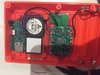 1.2 MB Views: 194
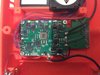 1.1 MB Views: 202
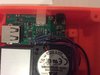 958.5 KB Views: 189