So, with the help of @Gman I finally decided on a project (well, he decided for me).
The idea is to make a synthesizer using purely (or at least primarily) digital logic in an FPGA. Ideally I'd also like to forgo the usage of wave-tables and mathematically derive some waveforms (notably sine) by integration. The realistic (though also optimistic) end result for the competition will involve an FPGA development kit, custom PCB, and a lot of head-banging in Modelsim to get my HDL working correctly.
I've already written a bunch of stuff about it for blog posts that I never made on my website so I'll just copy-paste some Word docs into here.
As a bonus here's a quick snippet of the write-up for the description of roughly how I'd like to create the oscillator banks:
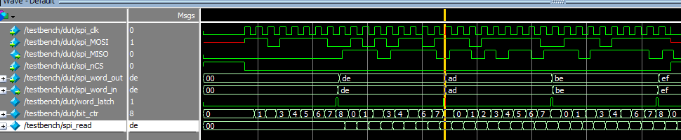
The rest is still a WIP and pending some Modelsim screenshots and code snippets.
Hopefully there will be further progress...
The idea is to make a synthesizer using purely (or at least primarily) digital logic in an FPGA. Ideally I'd also like to forgo the usage of wave-tables and mathematically derive some waveforms (notably sine) by integration. The realistic (though also optimistic) end result for the competition will involve an FPGA development kit, custom PCB, and a lot of head-banging in Modelsim to get my HDL working correctly.
I've already written a bunch of stuff about it for blog posts that I never made on my website so I'll just copy-paste some Word docs into here.
Once I have the PCB design and required functionality done if I have time I am open for other suggestions on added functionality. Any other feedback would also be greatly appreciated.Synopsis
Motivation
The world of synthesizers is vast and open for most to adventure into the realms of audio synthesis. Online anyone can easily find schematics for effects modules for synthesizers, diagrams and descriptions for how to make an oscillator, and pre-made modules to sync systems up with existing equipment. However, there doesn’t seem to be too much available in the realm of digital audio synthesis using solely digital logic. The idea of this project is to design, create, and make available a full working design for an FPGA-based digital music synthesizer. The design shall include all the core blocks in common sound chips including an oscillator, an envelope generator, a mixer and a MIDI controller.
Project Goals
Required Functionality
- The design shall be controllable through MIDI to allow ease of integration into existing systems.
- The design shall include a PCB with an integrated DAC.
- All elements of the design shall be open-sourced in the end.
Desired Functions
- At least 8 oscillator banks/channels.
- At least 3 waveforms per oscillator bank.
- ADSR envelope per channel.
- Ring modulation
- Nose generation
- At least 10 channels
- Internal effects chain (distortion/delay/etc.)
As a bonus here's a quick snippet of the write-up for the description of roughly how I'd like to create the oscillator banks:
...Initial Write-up
SYNTH PROJECT PART 1: OSCILLATORS
In the effort to reduce the number of block RAM bits used in the FPGA design and as an academic exercise an integrator approach to get fundamental waveform shapes will be taken. A square wave is trivial to implement in FPGA logic, it is simply a maximum and minimum value being toggled at a certain rate. Fortunately, a square wave integrated yields a triangle wave, and a triangle wave integrated yields a sine wave, or at least something visually/acoustically similar. However, there are some issues in discrete integration.
As you may remember from calculus class,
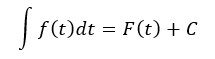
Where f(t) is your given function, and F(t) is the anti-derivative. There will exist some error or constant in a real-world integral. This can yield issues quickly when you notice we are chaining two integrals together; we would end up getting something as follow:
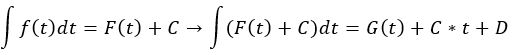
In short, integration errors add up quickly. Further, we also are running into another fundamental issue: this is all in the continuous time domain, but digital logic is discrete.
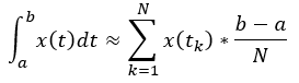
The second issue is easier to address. At my university analog signal processing is a prerequisite to taking digital signal processing. On the first day of class the teacher made a comment that DSP is mostly the same as ASP, but you replace all of the integrations with summations. So, in short, an integration in the discrete time domain is…just a bunch of additions. So now you can see:
Thus, we have the integrator as a summation. But what about that error? Well, in differential equations in general you can deal with error by dealing with (or modifying) the initial conditions. The same applies to the discrete domain. Calculation and application of initial conditions will hopefully solve some of these issues. As a second potential methodology of removing integration error a phase-locking approach can potentially be taken on the integrated value. Ideally in finding and subtracting phase error between the two signals the integration error can be mitigated.
So, in short, what's need is an accumulator and a multiplier to scale, then some way to get rid of potential errors in integration.
The rest is still a WIP and pending some Modelsim screenshots and code snippets.
Hopefully there will be further progress...