
kyler
.
- Joined
- Jul 30, 2019
- Messages
- 14
- Likes
- 4
I've been reading a lot of stuff on the site and lurking around a lot of the other worklogs of complete noobs like me while collecting parts and tweaking my design. But I've actually done some work on some things and I like feedback so,
In the words of our favourite plumber, here we go...
BOM
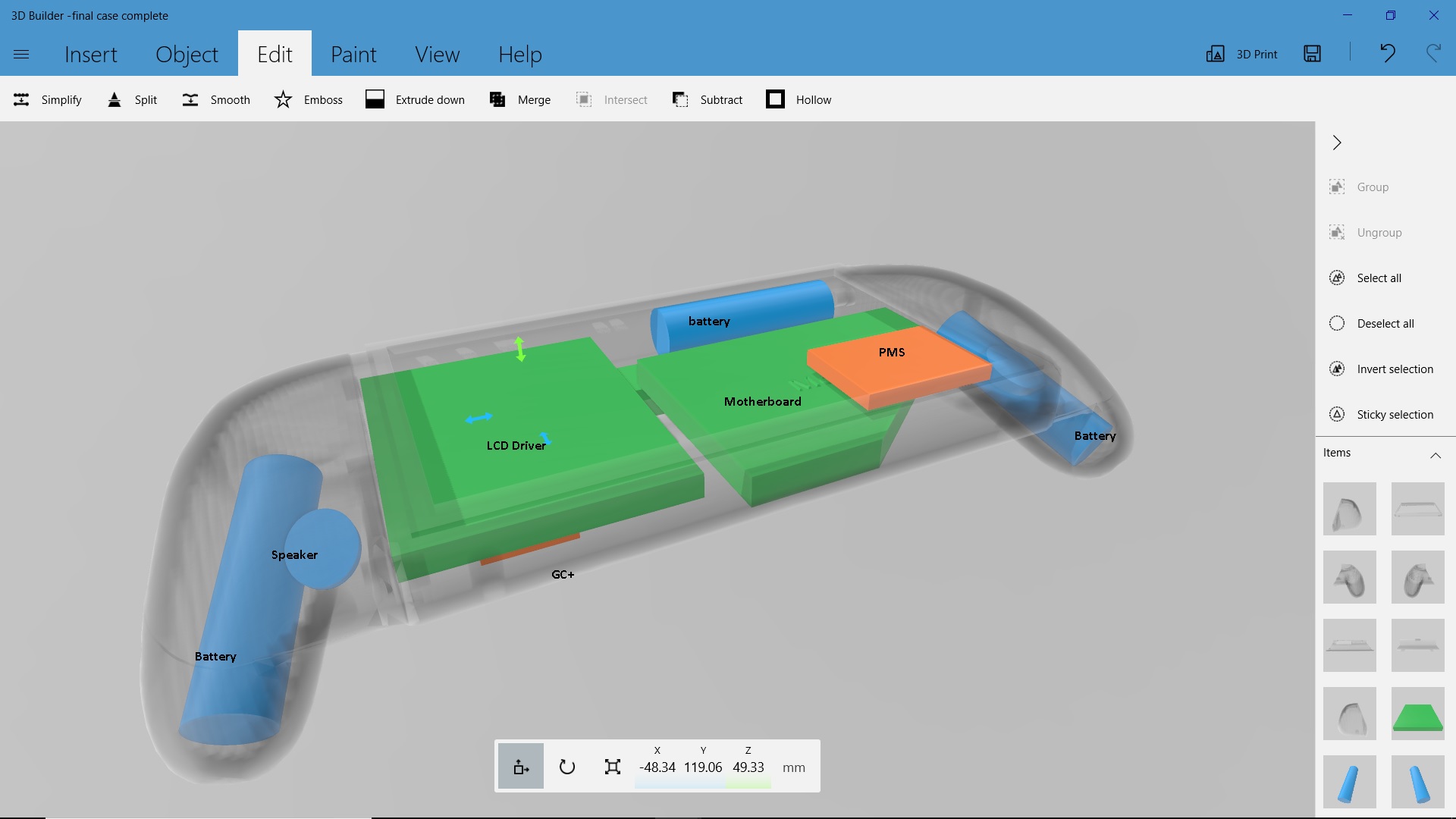
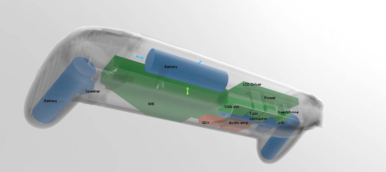
-Home made case
-OMGWTF-ed motherboard with MX chip and Bluetooth relocated
-LEDs for a sensor bar
-7 inch LCD with driver board (ER-TFTV070-5)
-PMS from the shop
-4 18650s in parallel
-GC+
-VGA port, USB port, headphone jack, 7 pin connector, Wii's original power jack
-Fan and heat sink from a sad broken laptop. Speakers also came from that laptop
-Generic 3W audio amp board.
- D pad, joy sticks, and L\R buttons from a broken aftermarket controller. I've got tact switches and a 3d printer for the rest
-Boost converter that I'm working on to take the 1S4P batteries and turn it into 12V for the screen and few other spots where I need 12V. It's still too rough and untested to share. Not actually needed. LCDs lie. 5v is fine.
- patience and deep breathing.
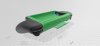
I've made the case from a scan of the switch pro controller because my goal is to make something that won't hurt my mangled, RSI-ridden hands. The pro controller is actually one of the few controllers that I can use without much regret, so that's where I started from. I then found a 3d mock up of the switch itself, because I knew I wanted something with a similar screen size. With a bit of digital hacking and slashing, I made a case.
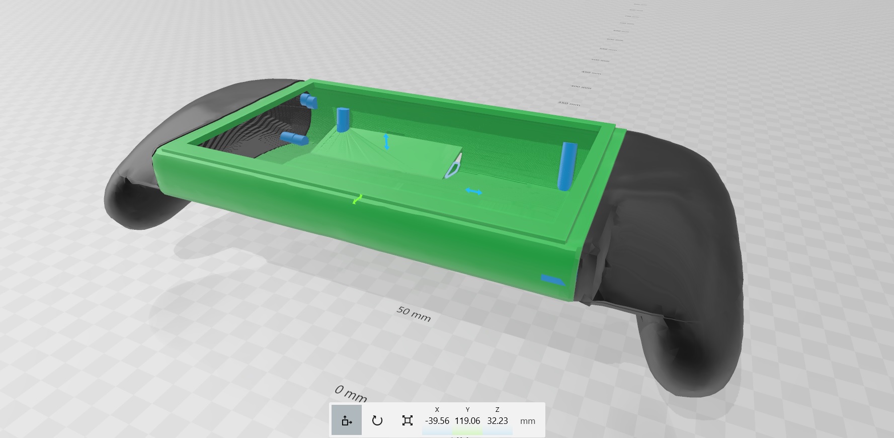
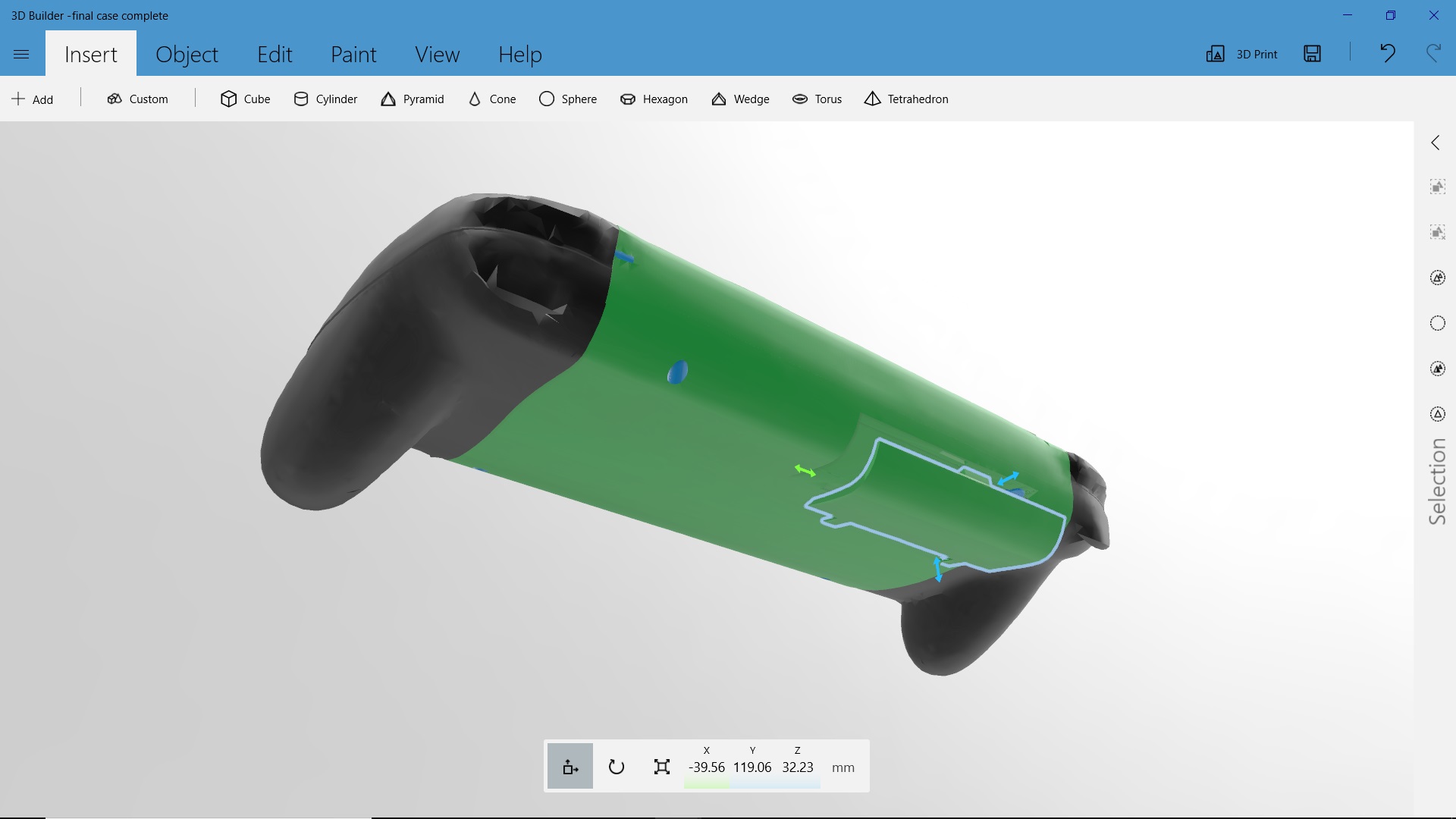
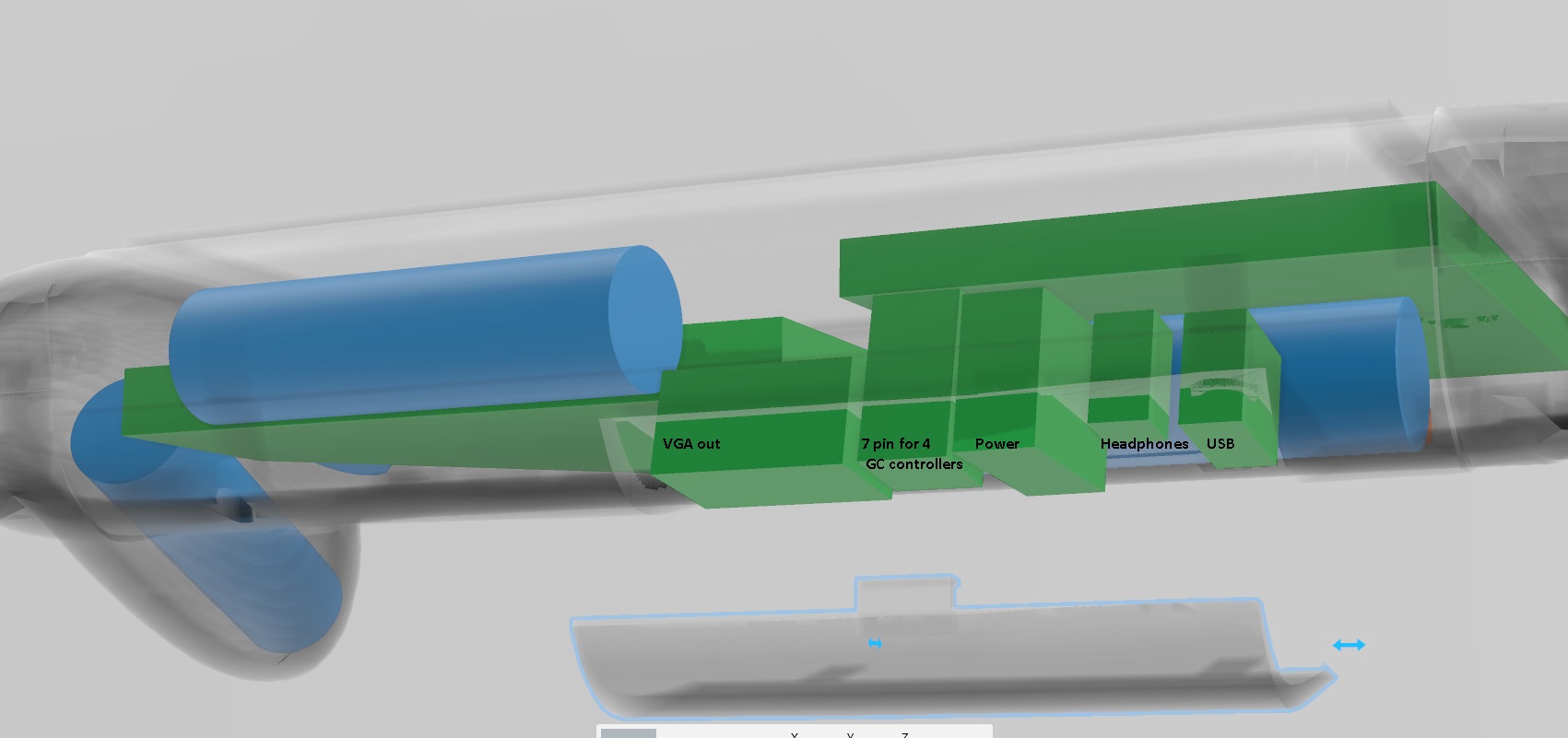
It's got a little battery cover type thing on the back, covering up the 5 ports on the system: a VGA out, USB, power, headphones, and a 7 pin connector. Because aesthetics. or something.
The plan is to make a dock where these ports will line up with their counterparts - VGA and headphone convert to HDMI and go go a TV, power will charge it, and the 7 pin connector will provide a connection to 4 external game cube controller ports. I'll have a button for turning off the screen for when a tv is being used, and a switch for disconnecting the hardwired controls and using an external controller for p1 instead. The dock will also hold the system so that the screen could be used if theres no TV available, and so that it can continue to be the sensor bar for wii games.
More or less its a switch. but a wii. so its what we wanted and expected the WII U to be. It kind of even looks like one. Except (hopefully) a little less fischer price. The shell is still a work in progress - a lot of my measurements have been estimates up until now, so some tweaking is happening. I'll probably also make some sort of internal frame to attach all the parts to and to guide wires. That way, when something breaks, it'll be a lot less painful to fix.
What's done?
- All parts obtained, except for the GC+ and the parts for the 3-4.2V to 12V boost board.
- Portablize mii installed
- a very rough cut of the motherboard and relocation of U10
- MX chip necessary parts destroyed while removing U10. Oops.
To do:
- relocate bluetooth
- Locate nice person willing to sell me MX chip portion of Wii board.
- Get GC+ when its in stock
- hardwire composite cable because im an idiot who forgot to install VGA patch
- install VGA patch
- Make voltage converter board.
- Finalize Case
- Attach all the things.
- put out (hopefully figurative) fires as they occur.
Later:
- make the dock.
Questions:
- am I missing anything?
- Assuming I make the circuit right, it's not stupid/ a bad idea/ actually impossible to boost 1S4P 18650s to 12V 2a, right? Based on what I've read, as long as I use batteries that can handle >2a draw each, 2a X 4 batteries = 8a, 8a X 3V (3v = dying 18650s) = 24w. the screen needs 12v X 2a = 24w. So long as the batteries can do even 2.5a continuous draw comfortably, that should provide more than enough for the needs of the screen and the boost converter itself/ any inefficiencies.
I then need to account for the draw of the wii too, but if we're talking just the screen, the above math does make sense? I think I'm oversimplifying something. I could just put the batteries in series, but I want to use Gman's PMS for the battery charging/ protection/ indicator led/ other converters, and it's strictly 1s.
- Anybody got a spare MX chip + necessary components they'd be willing to sell me? I'm in Canada, just FYI, for shipping purposes.
- I missed the GC+ being back in stock. Was waiting for payday. Is it going to be back again soonish? Will someone flash the PIC and sell it to me...?
- it also needs a name. Writing this, the Shii Guii (Shii-y Guii-y? Shiiee Guiiee? hmm pun might not work) popped into my head. Becuase it's shy about all those ports. I could make the vent for the fan a shy guy.
And well. I lurk.
I'll post pictures of the physical work once there's actually something to see.
Time to relocate some bluetooth.
In the words of our favourite plumber, here we go...
BOM
-Home made case
-OMGWTF-ed motherboard with MX chip and Bluetooth relocated
-LEDs for a sensor bar
-7 inch LCD with driver board (ER-TFTV070-5)
-PMS from the shop
-4 18650s in parallel
-GC+
-VGA port, USB port, headphone jack, 7 pin connector, Wii's original power jack
-Fan and heat sink from a sad broken laptop. Speakers also came from that laptop
-Generic 3W audio amp board.
- D pad, joy sticks, and L\R buttons from a broken aftermarket controller. I've got tact switches and a 3d printer for the rest
-
- patience and deep breathing.
I've made the case from a scan of the switch pro controller because my goal is to make something that won't hurt my mangled, RSI-ridden hands. The pro controller is actually one of the few controllers that I can use without much regret, so that's where I started from. I then found a 3d mock up of the switch itself, because I knew I wanted something with a similar screen size. With a bit of digital hacking and slashing, I made a case.
It's got a little battery cover type thing on the back, covering up the 5 ports on the system: a VGA out, USB, power, headphones, and a 7 pin connector. Because aesthetics. or something.
The plan is to make a dock where these ports will line up with their counterparts - VGA and headphone convert to HDMI and go go a TV, power will charge it, and the 7 pin connector will provide a connection to 4 external game cube controller ports. I'll have a button for turning off the screen for when a tv is being used, and a switch for disconnecting the hardwired controls and using an external controller for p1 instead. The dock will also hold the system so that the screen could be used if theres no TV available, and so that it can continue to be the sensor bar for wii games.
More or less its a switch. but a wii. so its what we wanted and expected the WII U to be. It kind of even looks like one. Except (hopefully) a little less fischer price. The shell is still a work in progress - a lot of my measurements have been estimates up until now, so some tweaking is happening. I'll probably also make some sort of internal frame to attach all the parts to and to guide wires. That way, when something breaks, it'll be a lot less painful to fix.
What's done?
- All parts obtained, except for the GC+ and the parts for the 3-4.2V to 12V boost board.
- Portablize mii installed
- a very rough cut of the motherboard and relocation of U10
- MX chip necessary parts destroyed while removing U10. Oops.
To do:
- relocate bluetooth
- Locate nice person willing to sell me MX chip portion of Wii board.
- Get GC+ when its in stock
- hardwire composite cable because im an idiot who forgot to install VGA patch
- install VGA patch
- Make voltage converter board.
- Finalize Case
- Attach all the things.
- put out (hopefully figurative) fires as they occur.
Later:
- make the dock.
Questions:
- am I missing anything?
- Assuming I make the circuit right, it's not stupid/ a bad idea/ actually impossible to boost 1S4P 18650s to 12V 2a, right? Based on what I've read, as long as I use batteries that can handle >2a draw each, 2a X 4 batteries = 8a, 8a X 3V (3v = dying 18650s) = 24w. the screen needs 12v X 2a = 24w. So long as the batteries can do even 2.5a continuous draw comfortably, that should provide more than enough for the needs of the screen and the boost converter itself/ any inefficiencies.
I then need to account for the draw of the wii too, but if we're talking just the screen, the above math does make sense? I think I'm oversimplifying something. I could just put the batteries in series, but I want to use Gman's PMS for the battery charging/ protection/ indicator led/ other converters, and it's strictly 1s.
- Anybody got a spare MX chip + necessary components they'd be willing to sell me? I'm in Canada, just FYI, for shipping purposes.
- I missed the GC+ being back in stock. Was waiting for payday. Is it going to be back again soonish? Will someone flash the PIC and sell it to me...?
- it also needs a name. Writing this, the Shii Guii (Shii-y Guii-y? Shiiee Guiiee? hmm pun might not work) popped into my head. Becuase it's shy about all those ports. I could make the vent for the fan a shy guy.
And well. I lurk.
I'll post pictures of the physical work once there's actually something to see.
Time to relocate some bluetooth.
Attachments
-
 174.4 KB Views: 243
Last edited: