Worklog First Micro attempt

Status
Not open for further replies.
Joined
Jan 17, 2018
Messages
28
Likes
9
20180301_230703.jpg
This is my first attempt at all of this, so I'm going to need all the help I can get!
My goal is to shrink a Wii for ease of transport while I travel .
  • Small size
  • Minimum number of "extras" to pack.
  • GameCube and Wii compatibility.
  • "Micro" design (no screen or onboard controls)
  • 5v power supply
  • HDMI out (for hotel use)
  • Integrated sensor leds.
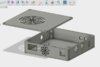
  • Probably 3d printing a case.
Here's what I've done so far.
I've read as many worklogs as I could absorb.
I found a cheap Wii 40 and installed PM.
Decased it.
Relocated U10 (that process sucks)
Relocated the Bluetooth card (that process sucks x10!!!!!!!!)
Sketched out the trim lines on the board.
Received all the parts for the custom regs, a socket for my 5v supply and a rocker switch for power.

So far it boots and runs!
Now it's time to assemble the regs and attempt my first trim.
Before I do that, I'm ready for advice and criticism! I included a photo of my board so far.
I tried to mimic the cut lines used by Gman and Jefflongo. Its a little different than the OMGWTF, so I'll have lots of questions about the wiring. I noticed that Jeff ran a 5v line to a contact near the fan connector (for the usb port?)
Should I snag an old laptop cooling fan?

Let me know if I posted this correctly!

Thought of another question: when building the custom regulators, I noticed that some people use 2 caps, while others only use one. On a non-battery system, is it ok to just use one cap?
 
Last edited:

jefflongo

Broke BitBuilt
Staff member
.
.
Joined
Dec 15, 2016
Messages
1,017
Likes
1,361
Location
Santa Barbara, CA
Portables
3
Looks good so far. Have you tested the bluetooth yet? I would try that before you trim. You can just use a candle or a sensor bar plugged into a different Wii to see if your wiimotes still work (protip: you can't sync wiimotes in postloader).

Before you trim, remove the big inductor on the trim line. You can just break it off with pliers. The trim is pretty much the same as OMGWTF, it just maintains those two ports and that extra screw hole (optional). The only thing to note is that you won't get audio unless you power the preamp or simply short the input and output of the preamp. If you check with a multimeter, you will see that that cap footprint I wired 5v to is connected to the 5v line. I could have just as well put 5v to the pins of the USB, it would have been the same thing.

The second cap is optional. I personally just prefer using the second one just in case. If you omit the second cap, I would at least put one cap on the 5v input.
 
Joined
Jan 17, 2018
Messages
28
Likes
9
The Bluetooth actually works! Looks like I'm ready to trim this. The audio/video section of the guide confuses the heck out of me. I didn't find any reference to powering the preamp. How do I power that sucker?
 

jefflongo

Broke BitBuilt
Staff member
.
.
Joined
Dec 15, 2016
Messages
1,017
Likes
1,361
Location
Santa Barbara, CA
Portables
3
The Bluetooth actually works! Looks like I'm ready to trim this. The audio/video section of the guide confuses the heck out of me. I didn't find any reference to powering the preamp. How do I power that sucker?
You can follow the trace for video/audio from the AVE chip all the way to the vias that send the signal to the top side of the board through those big caps, and out to the connectors on the board. You can wire up your video and audio to any point along that path (I like wiring to the output of the big caps for simplicity). However, the audio runs through the "preamp" (the 8 pin IC on the bottom of the board) which amplifies the audio. The L/R audio goes in, and an amplified L/R audio comes out. However, when we trim the board we no longer power the preamp with 12v. So you can either supplement your supply voltage (the audio quality gets worse the lower the supply voltage is) or remove the preamp all together and connect the input audio lines to an external audio amp or straight to the output audio lines. To power the preamp, just connect your supply voltage to the 12v pin marked on the trimming guide.
 
Joined
Jan 17, 2018
Messages
28
Likes
9
Since I'm leaving that section intact (Not removing the AV connector) is any of that necessary? I intend to output through the regular AV cable to a tv, not to an external set of speakers or video screen.
 

jefflongo

Broke BitBuilt
Staff member
.
.
Joined
Dec 15, 2016
Messages
1,017
Likes
1,361
Location
Santa Barbara, CA
Portables
3
Since I'm leaving that section intact (Not removing the AV connector) is any of that necessary? I intend to output through the regular AV cable to a tv, not to an external set of speakers or video screen.
No, it's not necessary. However powering the preamp or shorting the lines is necessary because in the current state after trimming the preamp will act as an open between the audio lines and the connector.
 
Joined
Jan 17, 2018
Messages
28
Likes
9
Ok. So, after the trim my AV connector will output video as it did before but without audio . I looked at the AV chip and followed the traces. Everything is inside the cut. Exactly which connections do I need to wire to restore sound?
Sorry to be dense on this, but I'm not seeing what's missing.
 

cheese

the tallest memer in town
Staff member
.
.
.
Joined
Mar 2, 2016
Messages
2,758
Likes
2,422
Location
Florida
Since the preamp isn't powered it won't output sound. Remove the preamp and connect across where it was (L in to L out, and R in to R out)
 
Joined
Jan 17, 2018
Messages
28
Likes
9
Ok. As I understand it, the preamp is normally powered by 12v. My 5v setup won't be enough to power this chip. Bypassing it will send audio to my AV connector. Is there a pinout somewhere showing which pins are which?

Btw, I just finished trimming my board. I'm not finding any dead shorts in any of the power lines so I think I'm safe to power it up once I finish my regulators.

Edit: I'm an idiot (sort of). I checked the Anatomy post to locate the preamp. I went back to the trimming guide and found the pinout. In my defense, the Trimming Guide doesn't identify that chip as the preamp. It must be taken for granted by experienced trimmers. Anyway, is it ok to just leave it in place and just jumper from leg to leg? I'm assuming from the guide picture, it's just connecting the pins labeled "1" and the same for the pins labeled "2" .
 
Last edited:

cheese

the tallest memer in town
Staff member
.
.
.
Joined
Mar 2, 2016
Messages
2,758
Likes
2,422
Location
Florida
Anyway, is it ok to just leave it in place and just jumper from leg to leg? I'm assuming from the guide picture, it's just connecting the pins labeled "1" and the same for the pins labeled "2" .
You could try that (won't hurt it), the audio may be a touch quiet though
 
Joined
Jan 17, 2018
Messages
28
Likes
9
20180303_062713.jpg
20180303_063024.jpg
Some progress!
I did the trim. I assembled my regulators. They are all putting out the correct voltages.
I wired it up and got no video. I beefed up the gauge of the supply wires. No video. (All of this was with an HDMI video converter).
I switched to straight component cabling and got video!
Here's where I'm at:
Sometimes it boots all the way.
Sometimes it boots the PM splash screen and goes to a blank screen.
Sometimes I get the intro followed by an exception message and then an upside down HB screen.
Others times I get nothing and it stays that way .
What's going on here?
All voltages are correct under load .
 
Joined
Mar 6, 2016
Messages
192
Likes
249
Try plugging the usb into the bottom port I forget if that causes issues or not. You also could try connecting 5v directly to the pin on the USB port
 

Nold

real emulation, no hardware
Staff member
.
.
2021 1st Place Winner
Joined
Jul 16, 2017
Messages
443
Likes
1,609
Location
EU
Portables
5 + 1*π
Hi,

looking at your pics, it looks like the bluetooth housing could touch the 1.8V line / LDO. As it's likely to be grounded, that would cause a short.

Also you should try cleaning up the solder joints on the PTHs & 3.3v on the wii. Make sure to heat the pad's long enoth, since bad solder joints can make trouble, too.
 
Joined
Jan 17, 2018
Messages
28
Likes
9
Thanks for the fast responses! This group is amazing!
The Bluetooth module has a healthy amount of hot glue under it, and was tested before the trim. No shorts there. I'll send a 5v line directly to the usb port. The usb stick was in that port in pre-trim testing. No boot problems at all. I'll heat up my connections and report back. BTW, I'm using a usb charger with 2.1amp output. Is that enough?

EDIT:
It's alive! The suggestion to run an extra 5v wire directly to the usb contacts under the socket did the trick. It boots every time now!
Next question: Has anybody had any luck getting a trimmed board to work with an HDMI adaptor?
It worked before the trim, but no video through the adaptor now. It's perfect through the component cable, but HDMI is far more common when I travel.

Edit:
Am I doing this correctly? (Editing my own posts?)
For the benefit of others, I'm posting my solution to the HDMI adaptor problem.
I ran 5v and 3.3v wires to the AV connections. The adaptor now works! The adaptor I use must draw power from the Wii connector.
 
Last edited:

Stitches

2 and a Half Dollarydoos
Staff member
.
.
Joined
Feb 5, 2017
Messages
3,812
Likes
3,004
Location
Banana Bender Land, Australia
Portables
6
Thanks for the fast responses! This group is amazing!
The Bluetooth module has a healthy amount of hot glue under it, and was tested before the trim. No shorts there. I'll send a 5v line directly to the usb port. The usb stick was in that port in pre-trim testing. No boot problems at all. I'll heat up my connections and report back. BTW, I'm using a usb charger with 2.1amp output. Is that enough?

EDIT:
It's alive! The suggestion to run an extra 5v wire directly to the usb contacts under the socket did the trick. It boots every time now!
Next question: Has anybody had any luck getting a trimmed board to work with an HDMI adaptor?
It worked before the trim, but no video through the adaptor now. It's perfect through the component cable, but HDMI is far more common when I travel.

Edit:
Am I doing this correctly? (Editing my own posts?)
For the benefit of others, I'm posting my solution to the HDMI adaptor problem.
I ran 5v and 3.3v wires to the AV connections. The adaptor now works! The adaptor I use must draw power from the Wii connector.
Editing posts rather than double posting is the prefered way yes, you're doing it right.
 
Joined
Jan 17, 2018
Messages
28
Likes
9
Minor update: I decided to go with a 3d printed case, so I've been working on that in fusion. I'm trimming down the stock heat sink to match the height of my case. I dug a small 5v fan out of an old laptop to cool this.
I picked up some ir leds and hooked them up to the board. They work great with the Wiimote. I spaced them at around 100mm and it works well from 6 ft away. I'll post some pictures when my case design is a little further along.

Latest problem!
I finally got around to putting some games on the usb stick. When I run a GameCube game, no problem! Perfect video and sound.
When I try to load a Wii game, I get a black screen and the Wii dies. The Wiimote disconnects immediately when the screen cuts out.

Any clues on this?
 
Last edited:

Stitches

2 and a Half Dollarydoos
Staff member
.
.
Joined
Feb 5, 2017
Messages
3,812
Likes
3,004
Location
Banana Bender Land, Australia
Portables
6
Minor update: I decided to go with a 3d printed case, so I've been working on that in fusion. I'm trimming down the stock heat sink to match the height of my case. I dug a small 5v fan out of an old laptop to cool this.
I picked up some ir leds and hooked them up to the board. They work great with the Wiimote. I spaced them at around 100cm and it works well from 6 ft away. I'll post some pictures when my case design is a little further along.

Latest problem!
I finally got around to putting some games on the usb stick. When I run a GameCube game, no problem! Perfect video and sound.
When I try to load a Wii game, I get a black screen and the Wii dies. The Wiimote disconnects immediately when the screen cuts out.

Any clues on this?
You might have the wifi enabled emuNAND on your USB. When you downloaded the pack, you didn't touch the wifi option, right?
 
Joined
Jan 17, 2018
Messages
28
Likes
9
no.
I ran games with PM on this usb before relocating U10, again after relocating Bluetooth. All was OK. After the trim I have a functioning Wiimote, the board boots 100% of the time into PM. My games show up in PM. Gamecube games run fine. Only the Emunand and Wii games cause a crash to a black screen. I also get the postloader "configuration file not found" warning each time. I choose the "create on USB" option each time. A known-working USB stick from another PM wii does the same thing. I noticed Neek2obooter loading on the other wii. The trimmed Wii dies without that loading screen ever coming up.

Just to rule out the usb, I moved all my files to a properly formatted Samsung 128gig usb.
Same result . I'm stumped.

Update:
With a ton of help from Cheese,I finally have this board working correctly. Here's what happened: When I initially softmodded the board with PM, it went through the whole process as the no-wifi option, but somehow the downloaded files had the wifi version of the Nand folder. Once I got the correct NAND it was able to boot Wii games. I also had to resync the wiimote while in a game and copy sysconf to get it to sync when a game is loaded.

Now that the board works, I threw together a case in Fusion 360. I picked up a new 3d printer last week, so now it's time to burn through some filament! I have all my parts ready, so I should be able to assemble this thing when the print is done.
wii case.jpg
wii case.jpg


All finished!
Here are some pics of the finished unit and a "FamilyPicture" to show the relative size of the games it replaces.
You can see the built-in sensor bar (IR LEDs). The power port is for a USB cable with a barrel connector so I can run it off a standard 5v
20180313_134134.jpg
20180313_134157.jpg
20180313_134211.jpg
20180313_134224.jpg
20180313_134235.jpg
20180313_140802.jpg
wii case.jpg
phone wall wart.
 
Last edited:

xsping

.
Joined
Dec 9, 2018
Messages
154
Likes
50
no.
I ran games with PM on this usb before relocating U10, again after relocating Bluetooth. All was OK. After the trim I have a functioning Wiimote, the board boots 100% of the time into PM. My games show up in PM. Gamecube games run fine. Only the Emunand and Wii games cause a crash to a black screen. I also get the postloader "configuration file not found" warning each time. I choose the "create on USB" option each time. A known-working USB stick from another PM wii does the same thing. I noticed Neek2obooter loading on the other wii. The trimmed Wii dies without that loading screen ever coming up.

Just to rule out the usb, I moved all my files to a properly formatted Samsung 128gig usb.
Same result . I'm stumped.

Update:
With a ton of help from Cheese,I finally have this board working correctly. Here's what happened: When I initially softmodded the board with PM, it went through the whole process as the no-wifi option, but somehow the downloaded files had the wifi version of the Nand folder. Once I got the correct NAND it was able to boot Wii games. I also had to resync the wiimote while in a game and copy sysconf to get it to sync when a game is loaded.

Now that the board works, I threw together a case in Fusion 360. I picked up a new 3d printer last week, so now it's time to burn through some filament! I have all my parts ready, so I should be able to assemble this thing when the print is done.
View attachment 5389 View attachment 5389

All finished!
Here are some pics of the finished unit and a "FamilyPicture" to show the relative size of the games it replaces.
You can see the built-in sensor bar (IR LEDs). The power port is for a USB cable with a barrel connector so I can run it off a standard 5v View attachment 5402 View attachment 5403 View attachment 5404 View attachment 5405 View attachment 5406 View attachment 5407 View attachment 5389 phone wall wart.
i can not use CAD, could you please upload the micro wii 3d print files?
 
Status
Not open for further replies.
Top