Worklog Final Destination Omega Trim

Wesk

Undervolting....
Staff member
.
.
Joined
Jul 12, 2017
Messages
868
Likes
2,167
Location
Queensland, Australia
So since the GC Nano project went into effect @CrazyGadget and I were working on more Omega trims than we've ever done before, this led me down a path of morbid curiosity to answer the question:

"How small can the Omega trim actually be?"

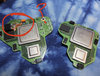
I spent a bit of time looking over the compendium and drew up a theoretical trim line for the smallest possible Omega footprint (without digging into voltage layers).
This trim would effectively make a "GC Pico" 16% smaller than the Nano and 32% smaller than the current world record.

1685359656520.png


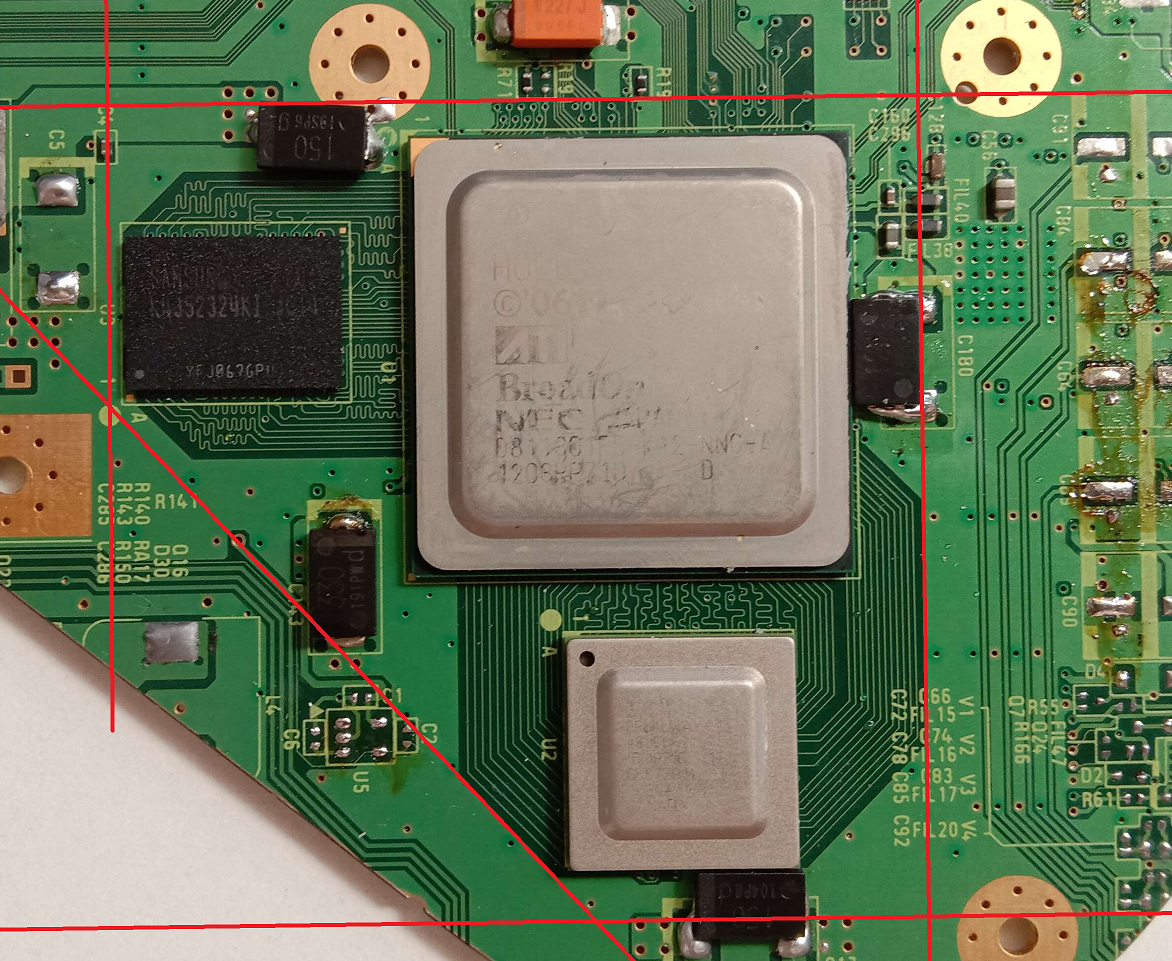
My first test was to relocate the 1.15v cap to the rear of the board and trim right up to the passives, leaving only a tiny sliver of the 1.15v via intact and have verified the Wii still boots.

1685359866588.png


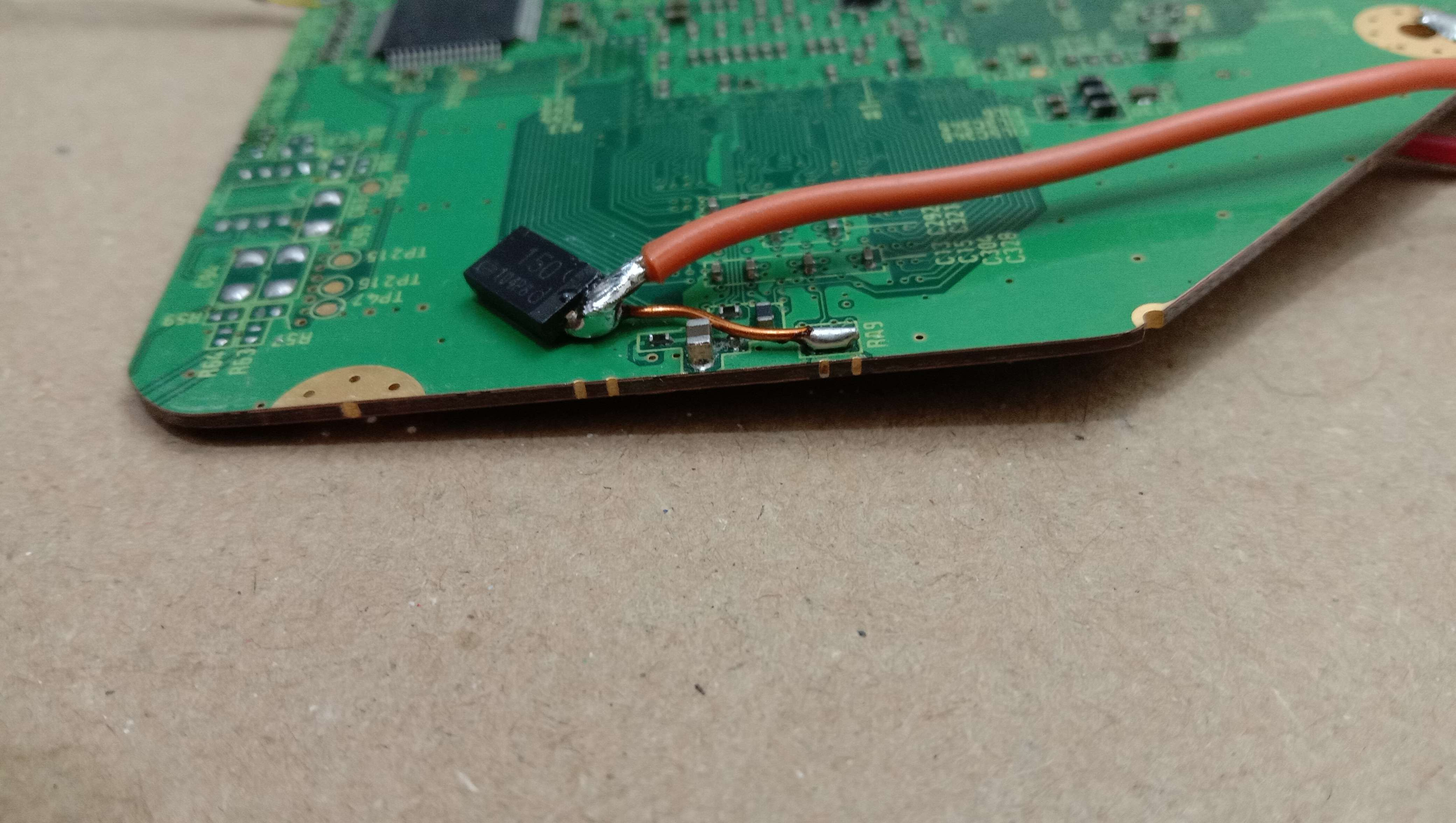
My next plan was to relocate the passives to the right of the GPU as most thought these were pretty much required for the system to boot.
@YveltalGriffin on the other hand was confident that these could be bypassed if 3.3v was applied to the correct pads.

1685360124872.png


He was right!, bypassing the components and supplying 3.3v directly the system booted right up and ran games without issue.

So we've now verified 3 of the trim lines are possible (RAM side doesn't change from a regular Omega).

The last line is the top but due to the NAND relocation flex sitting about 2mm higher than the potential trim line it can't be used which means I decided to go old school and manually rewire the Nand

1685360680592.png


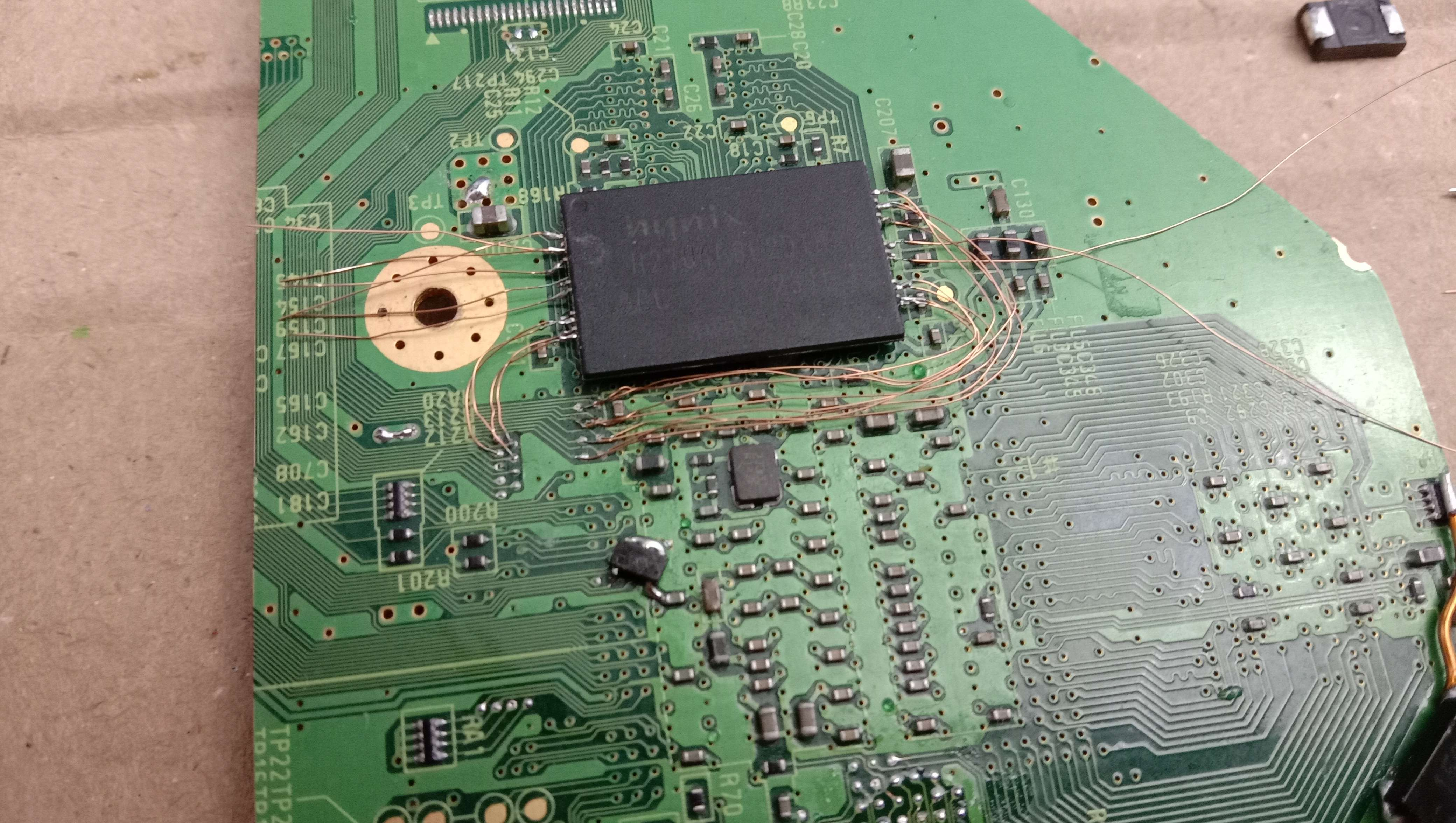
Unfortunately I was only about 8 wires away from finishing up the relocation when I realised I fucked up. I had accidentally removed pin 10 from the Nand while removing the non-required pins.

6c6.gif


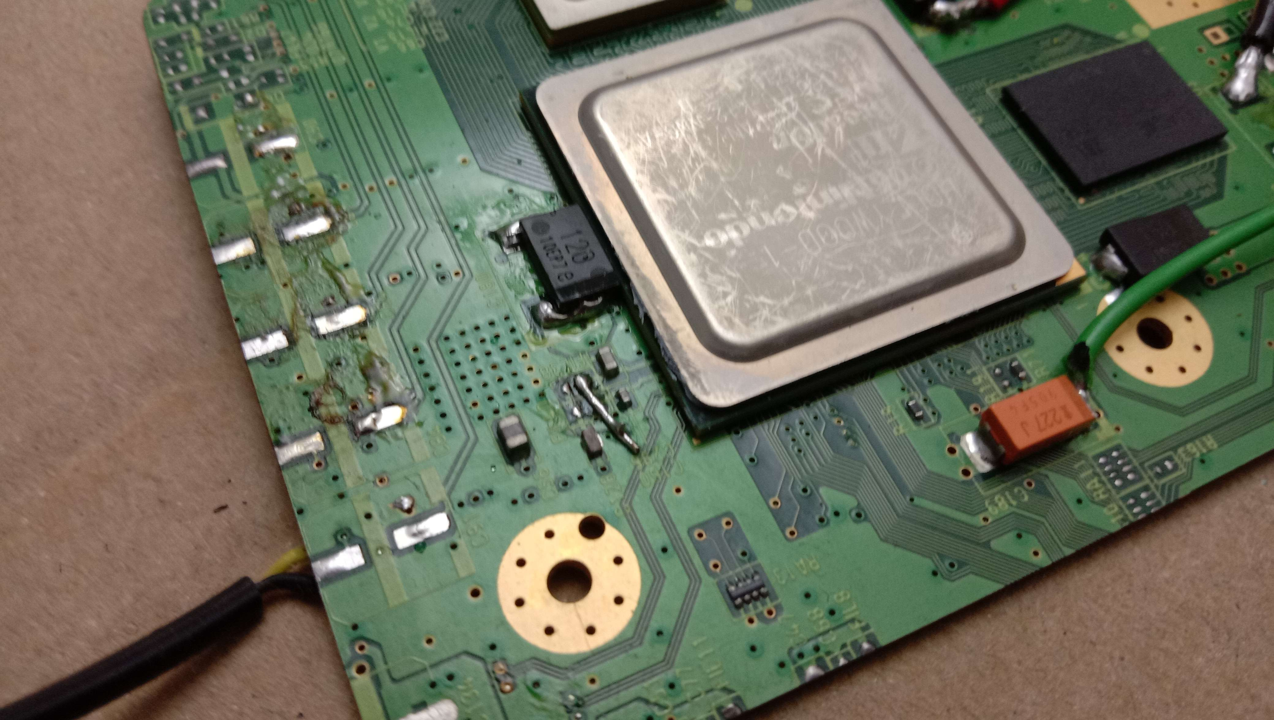
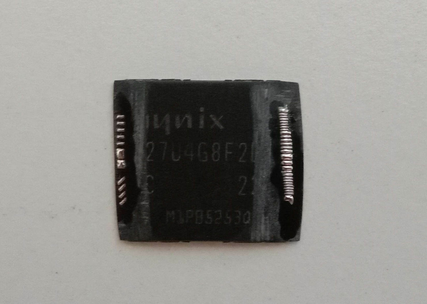
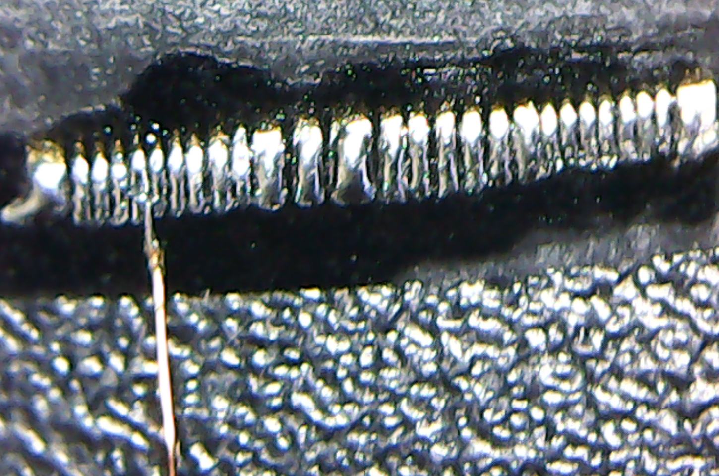
So I did what any sane person would do and was led to the 6th circle of hell (Heresy) by @Redherring32 and trimmed the Nand to get access to the leadframe, and it's about 40% smaller now.

1685361056299.png


The pitch on the leadframe is so fine that 40awg magnet wire barely fits on the pad.

1685361184351.png


I'm determined to have this Wii survive so once I've lost all my sanity soldering to this leadframe I'll update with my progress.
 

Viilmo

.
Joined
Jun 23, 2021
Messages
206
Likes
90
Location
Germany
Portables
1
One slip and its dead. Would love to see a gc pico tho and hoping the best with that nand.
Ngl a lot of chip trimming this year
 

Wesk

Undervolting....
Staff member
.
.
Joined
Jul 12, 2017
Messages
868
Likes
2,167
Location
Queensland, Australia
Update!

Because I am a weak, pathetic man I gave up on trying to solder to the leadframe of the nand. It's not impossible but my patience wears thin quickly.
If you thought wiring H+Vsync to the AVE was difficult check out this comparison between the pitches (Nand is also sitting closer to the camera making it seem larger).

1685579764782.png


So I moved over to an LMAO trim that I have used for testing things in the past, the only downside to this board is that I won't be able to trim the top line as far as I want as the nand flex sits too high.

I also decided to trim up a dead Wii trim I had laying around for an AVE donor board for relocation, we going old-school.


1685580127164.png


I performed an absolutely filthy relocation and verified the system was still booting:

1685580201614.png


Then came trim time:

1685580396421.png
1685580544606.png


It initially didn't boot but was quickly resolved by manually wiring 3.3v to this cap/via which then provides 3.3v to the bridged pads on top:

1685580712492.png
1685580775530.png


And here's the current trim sitting inside the GC Nano shell, keep in mind another 1.5mm-2mm could be trimmed off the top with a manual nand relocation:

1685581326995.png

step-brothers-room-for-activities.gif


So it's clear that we still haven't pushed the OMEGA as far as we can, anyone else keen to keep pushing?

It currently measures 53mm x 55mm, and 53mm x 53mm should be obtainable.
 
Last edited:

Wesk

Undervolting....
Staff member
.
.
Joined
Jul 12, 2017
Messages
868
Likes
2,167
Location
Queensland, Australia
Smaller again?

What if we were to relocate the zterm resistor and remove/relocate the decoupling caps for the RAM?

1685655433736.png


Verified the system still boots without the decoupling caps and have relocated the zterm resistor:

1685655541872.png


And trimmed:

1685655619032.png
1685655674719.png


Another millimeter trimmed for a width of only 52mm
 
Joined
May 31, 2023
Messages
17
Likes
0
Working on an Omega trim after completing a normal trim. What are these resistors on the LDO here and do you need the LDO at all? It's my understanding the LDO puts out 1.8V do I need to mimic that with a custom reg?
 

Attachments

Wesk

Undervolting....
Staff member
.
.
Joined
Jul 12, 2017
Messages
868
Likes
2,167
Location
Queensland, Australia
Working on an Omega trim after completing a normal trim. What are these resistors on the LDO here and do you need the LDO at all? It's my understanding the LDO puts out 1.8V do I need to mimic that with a custom reg?
If you have to ask you need to do more research. Omega is a "rite of passage" around these parts.
 

Wesk

Undervolting....
Staff member
.
.
Joined
Jul 12, 2017
Messages
868
Likes
2,167
Location
Queensland, Australia
Getting closer

Filtering components and pull-up resistor array for the CPU were trimmed from a donor board:

1685773195780.png


I found that there's a convenient 1.15v via just above the RA, it's not optimal for the amount of current on the 1.15v line but it means we don't have to dig to a voltage layer:

1685773364476.png


Filtering components and RA removed from Wii and relocation board mounted with the worlds most secure adhesive (hot glue) and wired:

1685773554810.png


Verified system is booting, and began trim:

1685773636730.png
1685773670660.png


Board now measures 52mm x 53mm, accounting for the top line that I cannot trim on this board we should see a final footprint of around 52mm x 51mm

Here's a footprint comparison with a typical OMGWTF trim:

1685774105515.png


I think it's someone else's turn to confirm the top trim line.

obama-mic-drop.gif
 

Shank

Moderator
Staff member
.
.
Joined
Jan 31, 2016
Messages
1,287
Likes
2,726
Portables
6
Score the top of the board. Board bend the RAM over onto the back of the board, leaving the back 2 layers connected. Use very short magnet wire to jumper the top RAM traces, and short thick wire to reconnect severed internal plane. It's something I've been thinking of for years but lack the willpower to execute it. Would be quite thick, probably too thick to be practical, but a hell of a meme. Working Wii with the footprint of (pretty much) just the CPU and GPU.
 

Wesk

Undervolting....
Staff member
.
.
Joined
Jul 12, 2017
Messages
868
Likes
2,167
Location
Queensland, Australia
So anyway, I began testin'

I had yet to actually test if this trim was stable, so I configured the system to automatically boot into F-Zero GX (no controller wired) as it has a decent loop of gameplay and FMV's.

There is a Wii under there somewhere:

1685864810134.png


F-Zero was successfully running and looping for approx 30-40mins before the video output went black, I'm not sure exactly when it failed as I was eating dinner at the time.

I tried power cycling the Wii but it had no life. Normally even if the system doesn't boot there is a small flicker over the composite line to indicate the AVE has fired up but that isn't happening either.

I've tested all the voltages on the PSU and there doesn't seem to be any issues there, so at this point the system is dead until I can potentially locate where the failure occurred.

rip-coffin.gif
 

Wesk

Undervolting....
Staff member
.
.
Joined
Jul 12, 2017
Messages
868
Likes
2,167
Location
Queensland, Australia
It lives!

it's alive.gif


After testing and reflowing a few joints it looks like it was related to the 1.15v via, I've reflowed it and secured the connection more and it's up and running again!

It's not surprising as there is a fair amount of current flowing through such a tiny via, possibly causing the joint to heat up and the solder connection to break.

I've got it looping F-Zero again and I'll keep an eye on that joint and see if it gets toasty.


1685922799865.png
 
Joined
Mar 20, 2023
Messages
41
Likes
26
Location
'Murica
Working on an Omega trim after completing a normal trim. What are these resistors on the LDO here and do you need the LDO at all? It's my understanding the LDO puts out 1.8V do I need to mimic that with a custom reg?
wrong thread, but yes the LDO converts 3.3V to 1.8V. You need a 1.8v regulator to solder onto the 1.8v vias on the board. this can be accomplished using the RVL-PSU PLUS since it has a 1.8v reg
 

Wesk

Undervolting....
Staff member
.
.
Joined
Jul 12, 2017
Messages
868
Likes
2,167
Location
Queensland, Australia
Stability issues....

So first off, seems the via I'm using for 1.15v may be a little too small as the solder joint kept breaking. This could be a number of things including thermal expansion/contraction or just a shitty connection on my behalf. Either way I decided to dig down into a voltage layer to make sure the 1.15v line had enough meat.

It aint pretty but it works.

1686029832051.png


Secondly the system does boot and run but seems to collapse at about the 30 minute mark with a hard lock. When this happens a full power drain needs to occur before it boots up again. This includes the composite line for whatever reason.

I'm gonna chalk the stability issues up to the filtering caps that were completely yeeted rather than relocated:

1686030255618.png
 
Joined
Sep 27, 2016
Messages
413
Likes
888
Wow, you really got this thing super tiny. Love the further research you have shared with us!
 

Wesk

Undervolting....
Staff member
.
.
Joined
Jul 12, 2017
Messages
868
Likes
2,167
Location
Queensland, Australia
Third time's a charm

I came across yet another half-complete trim in one of my many project boxes and this one is now destined for greatness.

With what I've learned from the previous trim I can optimise the build order/process which should make things far easier. I will also be keeping all of the RAM, CPU and GPU passives to hopefully resolve the stability issues the previous trim suffers from.

1686208294398.png


1.15v has been supplied directly to the voltage layer. RAM decoupling caps and zterm resistor have been relocated and the NAND flex has been used as a breakout for easier installation.

Next up is the relocation of the CPU passives (Filters and RA) and the GPU passives (Filters).​
 

Wesk

Undervolting....
Staff member
.
.
Joined
Jul 12, 2017
Messages
868
Likes
2,167
Location
Queensland, Australia
GPU/CPU components relocated

GPU filtering components relocated:

1686288067929.png


CPU filters/pullups relocated:

1686288136989.png


System is booting without issue so next step is to confirm stability before I go any further.
I'm going to leave Mario Kart DD looping for a couple hours which will at least be....
Count.gif

?four? times more stable than the previous trim​
 
Top