- Joined
- Nov 25, 2022
- Messages
- 89
- Likes
- 14
- Portables
- 1
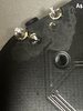
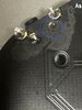
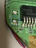
Alright so in my attempt to desolder the part on the driver board with my hot air station I accidentally knocked off multiple other parts -_- .
i attached a photo - are these parts important? I can try to put them back in place I guess.
i see where red and yellow go but I don’t know the proper orientation (like up or down - I don’t see any markings that would indicate which way)
blue and green I don’t really know what they are or where they went.
Am I better off getting a new board? What do you think
*****edit***** after thinking for a moment I can see where the parts go by looking at the old picture. I am still concerned about the orientation though
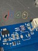
Attachments
-
 884.1 KB Views: 41
Last edited: