Worklog D_Crepp's Wii Micro

Joined
Oct 14, 2019
Messages
16
Likes
2
As I've posted in a couple of other places, I want to take a shot at building a Wii Micro. This build is inspired by @Gman and @jefflongo . Gman for coming up with the concept and perfecting it through his permutations of the Wii micro over time. Then Jeff's worklog broke down really well how to approach assembling the boards and setting a standard of laying all the components down in the case.

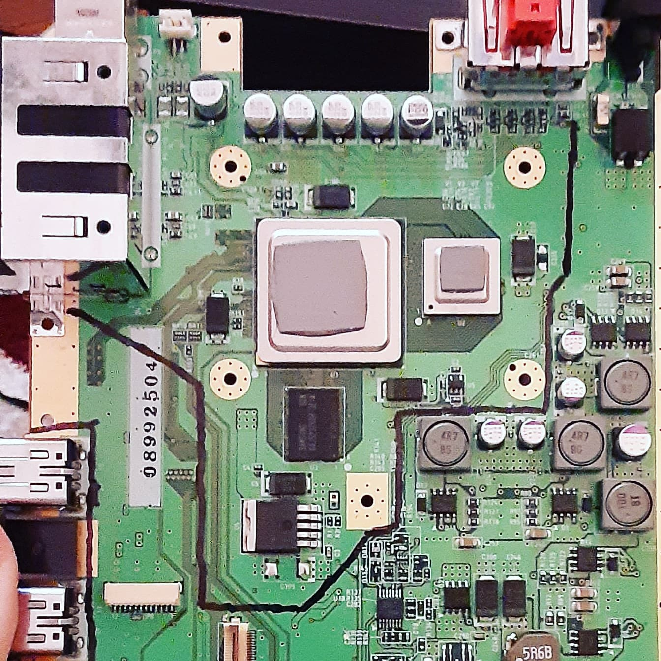
If I should I succeed, I will more likely build a portable later on. The board I will be using came from a white Wii console; counter-intuitively, the revision number on the board tells me it is a 4 layer board. (Images below) After some tweaking in MMM and a PortablizeMii install, this board runs Wii games fairly well enough for me to not need to buy another console. The features I would like my Wii Micro to have go as follows:

-GC Controller Ports and USB Ports (Obviously)
-Bluetooth Module and Sensor Bar compatibility
-Power and Sync buttons via hard tact switches or similar
-USB type C for power port
-Power Mii Regulator board...maybe? Please?
-40x40x10mm exhaust fan (possibly Noctua, space permitting)

I've read that original sensor bars need 12v for power but some of the newer ones can run off of just 5v? Or I'll more than likely resort to building my own sensor bar...

I have not relocated my U10 yet, because I'd like to know thoughts of people from this community who have experience as well as tips for soldering together small components/wires. Working with electronics is kind of a weakness for me at the moment, that's why I wanted to take a slightly smaller step into console modding rather than attempting a portable right away. Links to guides, comments, tips, anything helpful is appreciated in advance.
upload_2020-2-3_18-15-4.png
upload_2020-2-3_18-18-10.png
 

Attachments

Joined
Jan 8, 2020
Messages
87
Likes
16
So, the sensor bar CAN be torn down and rewired but it's just cheaper to build your own. Also, as far as your power and USB ports go, the USB C module in the Bitbuilt store is your best bet because you can access the internal USB drive and charge from the same port. Here is a good fan-https://store.cwc-group.com/udqfnkh11.html
The U10 is a pretty easy relocation, there's a video from Bitbuilt on YouTube about it for easier comprehension.
 

GingerOfOz

no wario
Staff member
.
.
2020 2nd Place Winner
2022 3rd Place Winner
Joined
Dec 16, 2016
Messages
1,122
Likes
2,709
Location
The Oregon Wildlands
Portables
just so many i am so cool
Your plan looks pretty good so far, your trim no so much.
TheTrimGuideExistsForAReason.jpg

Flip the board over and look at what that line is cutting straight through. Those traces would be the NAND traces, very important lines which you can't cut through without relocating the NAND. Cutting further inside than you need to is a bad idea if you don't know what you're doing, and there's especially no reason for you to be doing so here with how big your trim is already going to be with you maintaining all those ports.

As far as soldering guides, if you look in the Electronics 101 section of the forums there is a megathread with various videos, some of which help cover the basics of soldering. Good luck!
 

Shank

Moderator
Staff member
.
.
Joined
Jan 31, 2016
Messages
1,287
Likes
2,726
Portables
6
Ginger did a good job explaining it, but thought I'd reiterate: the cut lines in the trimming guide are not arbitrary. Just because you don't see anything, doesn't mean nothing is there. The cut lines are placed where they are for a reason, and are not merely suggestions. Experienced modders who do more advanced trims can only do so because they have a deep understanding of the Wii circuit board and its many layers
 
Joined
Oct 14, 2019
Messages
16
Likes
2
Okay, I see it in the LMAO and OMGWTF trims. I need to move that trim line over about another 6-12mm and clear all those traces around the hole; Ginger is correct, I don't want to relocate the NAND. I will fix the trim line when I get home.

I've Read the trim troubleshooting guide and will likely try to fit in my MX Chip in the Micro as well. Since the Wii can support emulators I'll try some N64 and possibly PS1/WiiSX once I complete this build.

I'm not fully understanding the function of the USB C module as suggested, can I get a more simplified explanation?
 

cheese

the tallest memer in town
Staff member
.
.
.
Joined
Mar 2, 2016
Messages
2,759
Likes
2,431
Location
Florida
I'm not fully understanding the function of the USB C module as suggested, can I get a more simplified explanation?
Basically,
  • If you plug it into a computer, you can access the files on an internally stored drive
  • If you plug it into a charger, it will charge the batteries
 
Joined
Oct 14, 2019
Messages
16
Likes
2
That's what I thought it, thanks for clearing that up. I don't plan on using batteries for this, just the USB-C port to get power from the wall. A simple little board from Adafruit or so should work fine, correct?

I've fixed my trim line, it looks close but I cut outside of the lines and sand closer to finish. I probably couldn't remove the U10/U9 chips with solder wick because of how tiny they are..? Then to cut the trace from the U5 and other things down the line, I'm going to invest in a fiberglass pen.

Edit: Tried uploading the pictures in this reply and a new one but I kept getting a login error...
 

GingerOfOz

no wario
Staff member
.
.
2020 2nd Place Winner
2022 3rd Place Winner
Joined
Dec 16, 2016
Messages
1,122
Likes
2,709
Location
The Oregon Wildlands
Portables
just so many i am so cool
You've fixed the issue around the NAND lines, but this new cut has you going ridiculously far in by where U10 is. You're cutting even into where the 1V are of the board is, which isn't even done on OMEGA trims.

Please stick to cutting outside the trim lines. You lack the necessary knowledge to know where to cut inside of the guide. If you show me another cut that looks bad I'm not going to correct you, you've been sufficiently warned prior to now.
 

Stitches

2 and a Half Dollarydoos
Staff member
.
.
Joined
Feb 5, 2017
Messages
3,817
Likes
3,011
Location
Banana Bender Land, Australia
Portables
6
So long as you cut in the middle of that line, you should be okay for NAND traces, but having 90 degree concave angles in your trim is a bad idea, very hard to sand. You're also getting mighty close to some required inner traces and passives, you should really use straight lines and keep it a bit closer to the guide's trim. If you trim it like that, that Wii is dead.
 

Shank

Moderator
Staff member
.
.
Joined
Jan 31, 2016
Messages
1,287
Likes
2,726
Portables
6
Ginger did a good job explaining it, but thought I'd reiterate: the cut lines in the trimming guide are not arbitrary. Just because you don't see anything, doesn't mean nothing is there. The cut lines are placed where they are for a reason, and are not merely suggestions. Experienced modders who do more advanced trims can only do so because they have a deep understanding of the Wii circuit board and its many layers
ಠ_ಠ
 
Joined
Oct 14, 2019
Messages
16
Likes
2
My apologies for the frustration I seem to be stirring, perhaps I should explain my thought process before I move on.

My intent was to start with the OMGWTF trim lines as depicted in the Wii Trimming Guide. Yes, I misplaced my first line and put it right over the NAND traces, but I've fixed that. That line turns 90 degrees to the edge of the board where the GC memory ports are to retain the USB ports on the other side. The cut line goes around the NAND, respective traces and over to the stock regulators, I make a 90 degree turn there to go around the component and then capture that fourth screw hole used for the heatsink. From there, cut over in between the power and analog ports to reuse the analog port.

I'm aware the cut line around the regulators gets too close for comfort with the traces just a hair over around the 1V pins and this is a good transition to my next thought.

having 90 degree concave angles in your trim is a bad idea, very hard to sand.
I am very aware that interior angle cuts are sketchy and awkward looking. I may be dense when it comes to electronics but if there's one thing I know how to do, it's making interior angle cuts with Dremels, x-actos, angle grinders, ect. For my smaller scale projects, I have a set of miniature files that are all about 3-4" long and they've served me well since I purchased them.
 

Gman

RTFDS
Staff member
.
.
.
.
.
Joined
Feb 25, 2016
Messages
1,437
Likes
2,887
Ok but why do a trim like that. Unless your case is a non rectangular shape, there is no advantage.
 
Joined
Oct 14, 2019
Messages
16
Likes
2
The only real advantage would be that much more space for other components (of which I not yet have) but I'm sure that can be respected.

The Case is rectangular, 154 x 120mm (judged by putting my calipers up to my untrimmed Wii and giving a little bit extra around the perimeter, so those overalls are subject change) and with the cover, 24mm tall.
upload_2020-2-5_21-58-2.png
 

cheese

the tallest memer in town
Staff member
.
.
.
Joined
Mar 2, 2016
Messages
2,759
Likes
2,431
Location
Florida
You're not saving yourself enough space by cutting that *very small* amount of board off to actually put any components there... Also, you can just put the stuff on top of the board. As for the internal angles on the cut, a file won't really help much since the bigger issue is that small pieces are hard to get out of internal corners, and shorts are very hard to see in the corners.

If you feel confident enough to make a custom trim, you should also be confident enough to troubleshoot any issues you will run into with said custom trim. Nothing against you, but it's extremely hard for us to work with a trim that you just randomly came up when trying to help, since we don't know what issues could come up if it's the trim or a different problem.
 
Joined
Oct 14, 2019
Messages
16
Likes
2
Those are very fair points....my apologies for the trouble. This first time, I will go ahead with the original trim and save the experimentation for another date. I'm still intending to keep the USB and Analog ports attached, though. Is it easier to remove the one regulator prior to trimming or just trim through it?

I still haven't even attempted relocating the U10, either. I'll try getting to that this weekend. Then once that's moved and tested successfully, board gets trimmed, and the way to test after that is with the custom regs. Is there a way to get the Power Mii Lite board? I don't see them in the shop but it would be a big help for someone still relatively new to soldering such as myself.
 
Joined
Oct 14, 2019
Messages
16
Likes
2
All right... So, I can solder wires to each other or to pads no problem, I cannot remove chips like the U10 very well. I only have solder wick and that removed a good bit of it, I think, but I still can't budge it without trying so hard as to break it. Would anyone recommend a hair dryer as an alternative to hot air?
 

splain

.
Joined
Mar 18, 2016
Messages
66
Likes
133
Don't use a hair dryer. It might actually be easier to ADD solder, so that you can more easily keep all the solder points warm while switching between them with your iron. Don't push/pull hard on the U10 or else you'll break it or lift pads. Be very gentle. Just look around the forums or on discord at the sheer volume of people who messed up their U10 relocation because they pushed too hard and ended up ripping stuff off the motherboard.
 
Joined
Jan 21, 2020
Messages
16
Likes
18
Don't use a hair dryer. It might actually be easier to ADD solder, so that you can more easily keep all the solder points warm while switching between them with your iron. Don't push/pull hard on the U10 or else you'll break it or lift pads. Be very gentle. Just look around the forums or on discord at the sheer volume of people who messed up their U10 relocation because they pushed too hard and ended up ripping stuff off the motherboard.
Agreed. From my own experience in just the past few days the legs on the u10 are VERY fragile. Put a big blob of flux on the u10 and remove as much solder as you can with your solder wick. Then you'll just have to alternate sides of the u10 with your soldering iron until it comes free. It definitely takes a lot of patience.
 
Top