Discussion Controller-on-a-chip

Joined
Jul 27, 2017
Messages
11
Likes
24
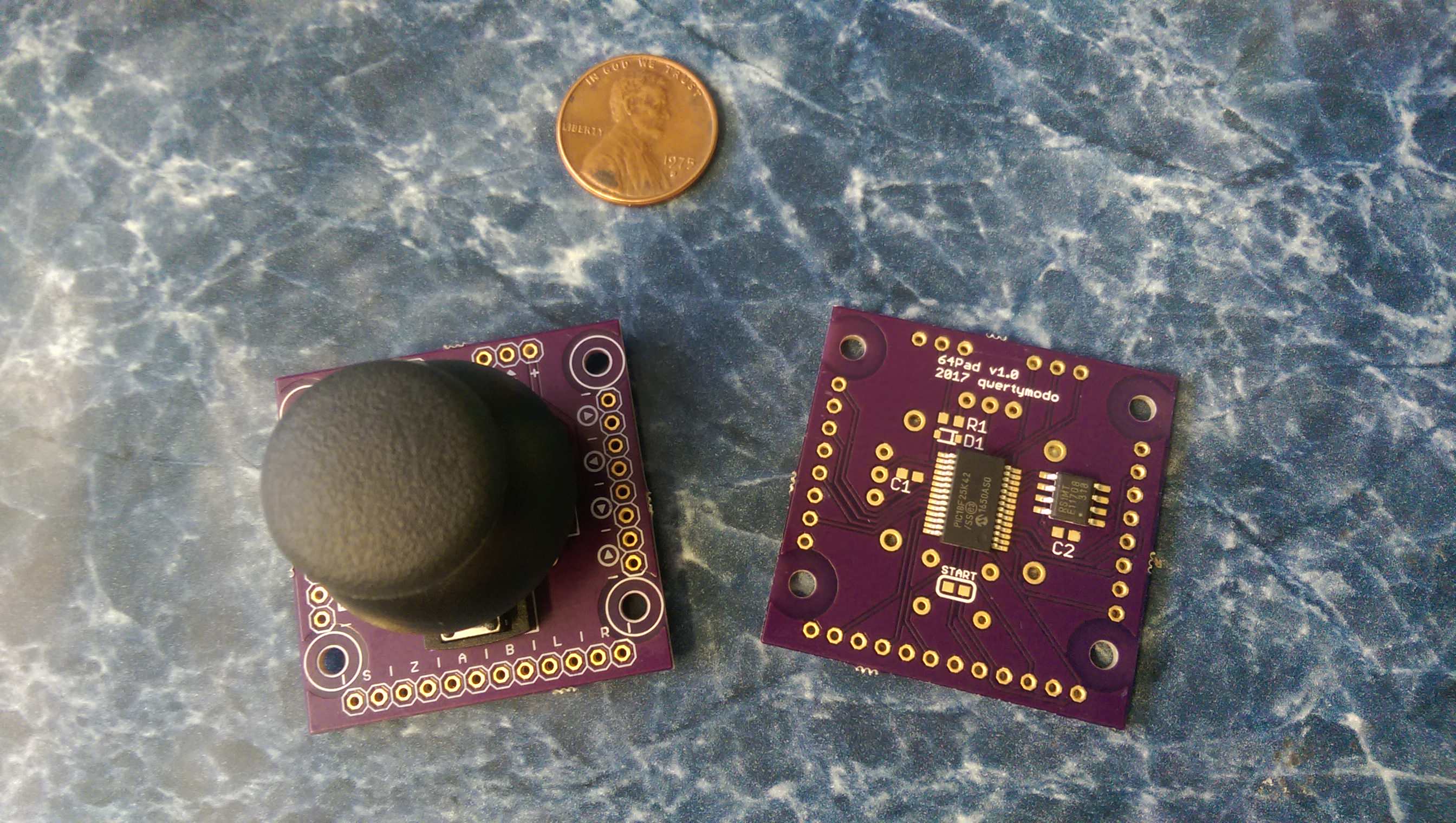
First post, ShockSlayer just introduced me to this board. Building a portable has been one of those projects I've always wanted to try, but it's a lot to take on, so I've taken it on in small pieces over the years. My latest mini project has been the controller. I've seen RDC's miNi64 boards, but I was looking for something built on an in-production chip more along the lines of this project. After playing around with it for a few weeks, I have most of the important pieces working, and sent out for PCB's. Of course, I discovered a schematic error that renders them useless 2 days after placing the order, but v1.1 boards should be coming soon. It uses a PS2 or GC joystick and includes an on-board 4x FRAM memory pak. It also supports rumble pak output, but I don't currently have the drive circuit figured out, so for now it's just a logic-level signal directly driven from an I/O pin. I might actually just leave it that way and offload the drive circuit to a separate board because that leaves the entire ICSP header accessible. I think it's pretty safe to say this is as small and simple as this is going to get. Just thought I'd share.
rf8QZWV.jpg
 
Last edited:

Gman

RTFDS
Staff member
.
.
.
.
.
Joined
Feb 25, 2016
Messages
1,437
Likes
2,887
This is great. Keep up the magic dude
 
Joined
Dec 28, 2016
Messages
107
Likes
833
Looks good, I am also building a controller chip based on Kinetis and some serial fram. If only there were cplds with dual adc...
 
Joined
Jul 27, 2017
Messages
11
Likes
24
I was actually pleasantly surprised that I was able to pull off the controller protocol by slightly abusing a UART instead of manually bit-banging the whole thing, which is what burned me out the last time I tried to make this work (writes were easy, but reads were cutting it super close at an 8MHz instruction clock). One thing I don't have much confirmation on is the maximum timing for mempak read/write ACKs. I'm able to buffer an entire mempak page (256 bytes) in ~500uS, and write it back in ~520uS, without the CRC, which is the last bit of hardware I still need to figure out on this micro, it actually has a CRC module. I'm hoping that's fast enough (and the few sources I've found online were saying 20ms which would be PLENTY of time...). Actually, I don't really understand the CRC all that well at all, so that may take me a bit.
 
Joined
Jul 27, 2017
Messages
11
Likes
24
I do have one question that I suspect the folks around here might have a good insight on, and that is the joystick sensitivity. I have seen a lot of vague information about translating the sensitivity of an analog stick to the original stick but not a lot of concrete details.

Here's what I know:

*Each quadrature pulse from the joystick translates to a value of +/-4 in the final output
*There appears to be roughly 18 pulses between centered and max in any direction, meaning the max value is approximately 0x48 (I'm on my phone and can't calculate the 8-bit two's complement in my head for the min, but it's just -0x48)
*There is no dead zone, except the physical/mechanical one that forms over time due to the stick wearing down (i.e. the chip on the controller doesn't ignore any quadrature pulses when it's near the center, it's just a direct 1:4 value)

Putting this all together, my suspicion is that the main problem is with sticks that report values on a much larger range than the originals did, especially if they're reporting a full 0x80-0x7F range. This is what I suspect the Wii VC does, for instance, trying to aim the cannon in Mario is almost impossible because the slightest tap moves it way too far. However, I also see people talking online about the dead zone. I've confirmed by removing the joystick and manually outputting quadrature pulses, followed by polling the controller, that the controller's IC does not implement any kind of firmware-level dead zone. Zero it out and send a single pulse and you get back 0x04, send another 0x08, so on and so forth. Direct 1:4 linear relationship across the entire range. So the only way for there to be a dead zone is due to mechanical wear, aka the infamous loose sticks. I suppose this could be emulated, but I don't see much point since the replacement sticks don't suffer the same flaw. Finally, because of the 1:4 output ratio, the output values are always (except right at init) mod 4 values. Should I mask off the bottom two bits? Is the inclusion of those two bits (resulting in a 4x increase in joystick resolution) at all responsible for the sensitivity issues people experience? It's just hard for me to know because, as I said, the discussions I've seen have been vague as to exactly what the issues *are*.
 

Aurelio

ᕕ( ᐛ )ᕗ
Staff member
.
.
.
.
.
Joined
Mar 3, 2016
Messages
2,229
Likes
2,952
Portables
2
I do have one question that I suspect the folks around here might have a good insight on, and that is the joystick sensitivity. I have seen a lot of vague information about translating the sensitivity of an analog stick to the original stick but not a lot of concrete details.

Here's what I know:

*Each quadrature pulse from the joystick translates to a value of +/-4 in the final output
*There appears to be roughly 18 pulses between centered and max in any direction, meaning the max value is approximately 0x48 (I'm on my phone and can't calculate the 8-bit two's complement in my head for the min, but it's just -0x48)
*There is no dead zone, except the physical/mechanical one that forms over time due to the stick wearing down (i.e. the chip on the controller doesn't ignore any quadrature pulses when it's near the center, it's just a direct 1:4 value)

Putting this all together, my suspicion is that the main problem is with sticks that report values on a much larger range than the originals did, especially if they're reporting a full 0x80-0x7F range. This is what I suspect the Wii VC does, for instance, trying to aim the cannon in Mario is almost impossible because the slightest tap moves it way too far. However, I also see people talking online about the dead zone. I've confirmed by removing the joystick and manually outputting quadrature pulses, followed by polling the controller, that the controller's IC does not implement any kind of firmware-level dead zone. Zero it out and send a single pulse and you get back 0x04, send another 0x08, so on and so forth. Direct 1:4 linear relationship across the entire range. So the only way for there to be a dead zone is due to mechanical wear, aka the infamous loose sticks. I suppose this could be emulated, but I don't see much point since the replacement sticks don't suffer the same flaw. Finally, because of the 1:4 output ratio, the output values are always (except right at init) mod 4 values. Should I mask off the bottom two bits? Is the inclusion of those two bits (resulting in a 4x increase in joystick resolution) at all responsible for the sensitivity issues people experience? It's just hard for me to know because, as I said, the discussions I've seen have been vague as to exactly what the issues *are*.
While I was working on the N64+ I saw a range going from -0x50 to 0x50. I just scale the range of the joystick so that it outputs a range of -0x50 to 0x50, then I clamp it to that range just to be safe. I also implement a deadzone on the raw analog data read from the joystick. On the GC+ I have it configurable from a homebrew, on the N64+ I wasn't 100% how I was going to handle that.
Also I didn't care at all about the two LSBs and I have no sensitivity issue.
 

Miceeno

.
2020 3rd Place Winner
Joined
Nov 30, 2016
Messages
153
Likes
281
Portables
6


I need one of these for my in-progress portable. Any chance these with be available to buy?

I have been considering using a GC replacement board with a GC to N64 adapter if these aren't good to go.
 
Joined
Jul 27, 2017
Messages
11
Likes
24
I plan to complete the project and I plan to make them available. Whether that means selling them or just releasing everything open source, I don't know yet. If I sell them, the price will likely be around $20 + shipping, which will include the fully populated PCB, 4x memory card, and a GC-style joystick with the cap (like the ones on micro's converters). If people want, I might be able to offer it with a 1x card or no card for a bit cheaper. Right now pretty much all that's left is to figure out the CRC for data transfers and then write the top-level control logic to put everything together.
 

Aurelio

ᕕ( ᐛ )ᕗ
Staff member
.
.
.
.
.
Joined
Mar 3, 2016
Messages
2,229
Likes
2,952
Portables
2
I plan to complete the project and I plan to make them available. Whether that means selling them or just releasing everything open source, I don't know yet. If I sell them, the price will likely be around $20 + shipping, which will include the fully populated PCB, 4x memory card, and a GC-style joystick with the cap (like the ones on micro's converters). If people want, I might be able to offer it with a 1x card or no card for a bit cheaper. Right now pretty much all that's left is to figure out the CRC for data transfers and then write the top-level control logic to put everything together.
For the crc you can use a lookup table and basically just perform a xor
 
Joined
Jul 27, 2017
Messages
11
Likes
24
I know, I've seen that mentioned a few times, but I don't actually understand how it's done or how to go about pre-computing the table. Also, this chip has a CRC module and I kind of like the idea of using the available hardware (good learning experience too).
 

Aurelio

ᕕ( ᐛ )ᕗ
Staff member
.
.
.
.
.
Joined
Mar 3, 2016
Messages
2,229
Likes
2,952
Portables
2
I know, I've seen that mentioned a few times, but I don't actually understand how it's done or how to go about pre-computing the table. Also, this chip has a CRC module and I kind of like the idea of using the available hardware (good learning experience too).
The crc hardware integrated in PICs is quite fast, but for CRC8 the look up table is way faster.
If you want in the next days I can share with you the code I made for the N64+. It’s based on the PIC18F25K22, so it should be easily to port
 
Joined
Jul 27, 2017
Messages
11
Likes
24
That would be great. I'm using the 18F25K42, so it should just drop right in without any porting (assuming you're using XC8, not C18, but even that wouldn't be hard).
 

Aurelio

ᕕ( ᐛ )ᕗ
Staff member
.
.
.
.
.
Joined
Mar 3, 2016
Messages
2,229
Likes
2,952
Portables
2
That would be great. I'm using the 18F25K42, so it should just drop right in without any porting (assuming you're using XC8, not C18, but even that wouldn't be hard).
Ayy no, it’s all in asm :D
 
Joined
Jul 27, 2017
Messages
11
Likes
24
Of course it is. :P Might just be easier to write it myself from the pseudocode here.

Code:
while(augmented message not exhausted) {
    Control = messagebyte
    messagebyte = next_messagebyte()
    messagebyte = messagebyte XOR table[Control]
}

CRC = messagebyte
 

Aurelio

ᕕ( ᐛ )ᕗ
Staff member
.
.
.
.
.
Joined
Mar 3, 2016
Messages
2,229
Likes
2,952
Portables
2
Of course it is. :P Might just be easier to write it myself from the pseudocode here.

Code:
while(augmented message not exhausted) {
    Control = messagebyte
    messagebyte = next_messagebyte()
    messagebyte = messagebyte XOR table[Control]
}

CRC = messagebyte
Yeah that’s pretty much what my asm code does. I had to use asm for proper timing of the communication protocol. I did that with GC+ and then I just adapted the code to N64+ :D
 
Joined
Jul 27, 2017
Messages
11
Likes
24
Yeah, I totally get why you'd do it in asm, but that's a big part of the reason I never finished any of my previous attempts at this project. This time around I decided to try implementing the data protocol by abusing a UART which ended up working surprisingly well, despite a 16% duty cycle error (the bit period is still dead on 4uS thanks to also abusing OSCTUNE, but the bits are sent out as 0.8/3.2uS instead of 1/3uS... seems to work fine though). Along with the fact that this chip has a 2-byte FIFO and a 64MHz oscillator (16MHz instruction cycle) gives me plenty of headroom to do everything in nice, readable C.

The data CRC, I understand well enough. For a read, the console sends 3 bytes, the controller sends 32 data bytes + CRC, for a write, the console sends 35 bytes and the controller responds with a CRC of the 32 data bytes. But how is the address CRC handled? What happens if the address CRC is incorrect? Does a read return dummy data? Does a write simply get ignored? What data CRC does the controller return in this case?
 
Joined
Jul 27, 2017
Messages
11
Likes
24
Just in case anybody is interested in how I'm handling the data protocol on the UART, it's 2 N64 bits per UART byte, 1.25MHz baud rate.

00 => 0x08
01 => 0xE8
10 => 0x0F
11 => 0xEF

I made up a quick diagram to illustrate, and show where the duty cycle error occurs. Note that the N64 is MSB first and UART is LSB first.

UART.png
 
Top