
- Joined
- May 10, 2019
- Messages
- 23
- Likes
- 15
Hi everyone! I'm finishing a library for the controller chip, so I can make a custom board using it, for me at least it will be very useful, if anyone is interested, I may upload it here.
It's not hard to do, I know, but it's boring, takes some hours of our days lol.
Of course I still have to test it on a printed board to see if the pads are really alligned, but they do seem in place.
I'm using as a reference the controller pinout from here.
I intend on doing a smaller board, and pinout for the controller pak I modded to not use batteries. Do you guys think it's worth it?
Edit 1:
Edit 2:
Edit 3:
It's not hard to do, I know, but it's boring, takes some hours of our days lol.
Of course I still have to test it on a printed board to see if the pads are really alligned, but they do seem in place.
I'm using as a reference the controller pinout from here.
I intend on doing a smaller board, and pinout for the controller pak I modded to not use batteries. Do you guys think it's worth it?
Edit 1:
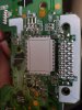
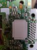
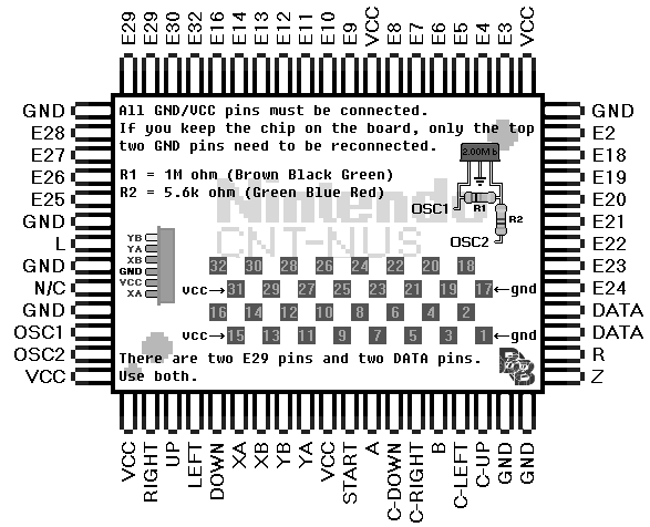
Since I plan on making the custom board, I mapped the controller pak as in the image:
Pins are as follow.:
The U1 chip, named PWIC, seems to be a step down, but I didn't find anything about it online yet, 99% sure it's just a converter.
The bigger white box named C1 connects to pin 31/15 VCC, and to ground. Not sure if any of those are necessary to function, or if the chip can work on it's own, when connected to the E-pins.
As far as I can tell, the FM28V020 works by putting it in place, that's what I tested. By it's datasheet, pin 28 really is VCC and it works off of 2,0 to 3,6 V, and should be 3,3V.
The datasheet also says.:
"A 0.1uF decoupling capacitor should be placed close to pin 28 (VDD) and the ground side of the capacitor should be connected to either a ground plane or low impedance path back to pin 14 (VSS). It is best to use a chip capacitor that has low ESR and has good high frequency characteristics."
Pins are as follow.:
1 = E2
2 = E3
3 = E4
4 = E5
5 = Battery? Have to test more
6 = E7
7 = E8
8 = E9
9 = E10
10 = E11
11 = E12
12 = E13
13 = E16
14 = GND
15 = E32
16 = E30
17 = E29
18 = E28
19 = E27
20 = N/C
21 = E26
22 = E25
23 = E24
24 = E23
25 = E22
26 = E21
27 = E20
28 = Seems to be VCC
2 = E3
3 = E4
4 = E5
5 = Battery? Have to test more
6 = E7
7 = E8
8 = E9
9 = E10
10 = E11
11 = E12
12 = E13
13 = E16
14 = GND
15 = E32
16 = E30
17 = E29
18 = E28
19 = E27
20 = N/C
21 = E26
22 = E25
23 = E24
24 = E23
25 = E22
26 = E21
27 = E20
28 = Seems to be VCC
The U1 chip, named PWIC, seems to be a step down, but I didn't find anything about it online yet, 99% sure it's just a converter.
The bigger white box named C1 connects to pin 31/15 VCC, and to ground. Not sure if any of those are necessary to function, or if the chip can work on it's own, when connected to the E-pins.
As far as I can tell, the FM28V020 works by putting it in place, that's what I tested. By it's datasheet, pin 28 really is VCC and it works off of 2,0 to 3,6 V, and should be 3,3V.
The datasheet also says.:
"A 0.1uF decoupling capacitor should be placed close to pin 28 (VDD) and the ground side of the capacitor should be connected to either a ground plane or low impedance path back to pin 14 (VSS). It is best to use a chip capacitor that has low ESR and has good high frequency characteristics."
Edit 2:
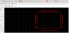
So I will make/have someone to make this board, here it's a picture of it, if it works I will share here the board layout + the libraries I made for the project (The cap I will use is not ideal on the memory chip, but here it's hoping lol).
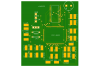
The buttons placement is a mess, didn't have much time to organize that, the board can probably be made smaller, but I'm not particularly good at this board designing thing.
I could share the groundings, I could make the analog connections pins instead of pads... And a lot of other improvements.
Anyway let's see if it works...
Edit 3:
So, while I wait for MONTHS, for the board to arrive in my country, I will list a few things here for a next revision of this board:
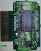
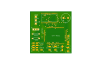
Here it's a picture of the new board design, without the unecessary ground pads.
- Integrate the board with the analog solution for the N64 (Analog stick, micro controller etc)
Redo (remove) the many ground pads, which are unecessary space on the boardDONE- Release the files on my github page
- Release a bonus design which I'll use on my own portable, integrating all the buttons, aswell as the analog sticks in one board, ready to be placed on case.
- Add also the rumble functionality aswell as the already present on the board controller pak, but since I don't have those clone paks that have this functionality, I won't do this for now. But will be a nice feature.[/S]
Here it's a picture of the new board design, without the unecessary ground pads.
Last edited:
")
