
LexRsnow
.
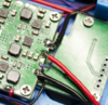
After our G-boy kit finally arrived, my father and I have been putting our portable together. However, once we reached "Step 13" of the G-boy tutorial, I noticed some conflicting images...
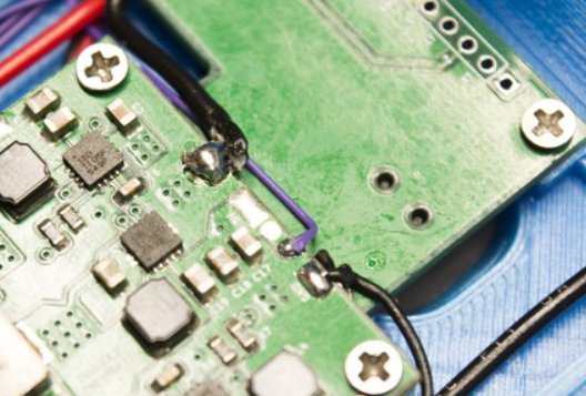
This is how the wires are soldered on "Wiring the USB-C PCB" Step 3 (1st)
But this is how they are arranged on "Wiring the RGB LED PCB & LCD Power" Step 2: (3rd)
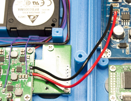
Which is contradictory to an image on the later aforementioned step (2nd)
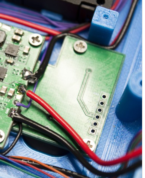
Notice how in one picture, the very top black wire is present, but then is missing in the latest picture (NOTE: The pictures are labeled with numbers in the order of appearance in the manual). You can tell it is missing by looking at the "tail" of the top black wire and seeing how it changes from the picture labeled "3rd."
If someone could correct me, or lead me to the right way to solder these wires, please help.
This is how the wires are soldered on "Wiring the USB-C PCB" Step 3 (1st)
But this is how they are arranged on "Wiring the RGB LED PCB & LCD Power" Step 2: (3rd)
Which is contradictory to an image on the later aforementioned step (2nd)
Notice how in one picture, the very top black wire is present, but then is missing in the latest picture (NOTE: The pictures are labeled with numbers in the order of appearance in the manual). You can tell it is missing by looking at the "tail" of the top black wire and seeing how it changes from the picture labeled "3rd."
If someone could correct me, or lead me to the right way to solder these wires, please help.
Attachments
-
 891.2 KB Views: 70
 -
 471.2 KB Views: 69