Worklog My first portable; Ashida

Retro95

.
2023 3rd Place
Joined
Mar 29, 2023
Messages
180
Likes
235
Location
Oregon
Portables
2
Hey guys!

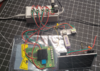
I got a little cocky and decided I'd build an Ashida (my first portable) without testing it any ANY STEP along the way. This obviously led to me having an Ashida that did NOT work. I tore it all apart and I am now bench building the portable before throwing everything into a case.

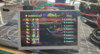
I have got my 3rd Wii trim (killed the first 2) fully functional with AV video, USB booting, GameCube controller input and have ran a couple races in double dash to confirm USB doesn't crash during gameplay.

I've now wired the Ashida IPS screen benchtop style too (powered by external variable power supply) and cannot get the VGA video input to work. I have ordered a second screen driver board on 4layers in case it's the board...

I have performed the following for VGA:
  • My Wii was not patched for VGA during RVloader install (I kept AV functionality for bench testing)
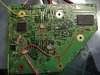
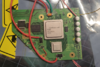
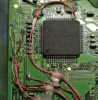
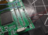
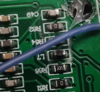
  • In order to achieve VGA I have soldered a 28awg stranded wire from TP47(pin8) to 3.3v on the board, and confirmed TP47(pin8) is receiving ~3.3volts. I also confirmed this prevents the device from outputting in AV video during boot up.
  • Pins/Traces 11, 9, 7, H-sync, V-sync wired to their corresponding places on the driver board
    • I am referring to the pins/traces by # from the official OMGWTF trim guide
  • All video wires are done with 32awg magnet wire. The video wires are tightly wound with their own individual grounds.
  • I have taken resistance checks and have no shorts from video to GND, and from video chip on Wii to screen each solder point is <0.5ohms
Just to take it a step further I went ahead and wired AV video to the driver board, and a momentary button to "SOURCE" on the screen and was able to change input to AV1 and got video! That doesn't 100% rule out the driver board as I am sure that VGA, AV1, AV2 use different traces/circuits on the board and the VGA portion may be bad (Driver board came in the mail with some funky oxidation around a lot of the caps/resistors)

Can someone double check me? I may be missing something staring me right in the face....
 

Attachments

Last edited:
Joined
Dec 6, 2020
Messages
226
Likes
260
Location
Canada
Portables
3
So you didn't install the vga patch, and are expecting to get vga by wiring mode to 3.3v, no patch means mode to 3.3 is outputting component video. Vga doesn't work without the patch installed and it does not overwrite the use of being able to have composite video to test. So rerun the installed using composite video and try vga again
 

Retro95

.
2023 3rd Place
Joined
Mar 29, 2023
Messages
180
Likes
235
Location
Oregon
Portables
2
Ah! well that makes sense. For some reason I misread/interpreted the VGA patch as it forces VGA/disables AV.

I'll get the patch installed again with VGA and update this thread after testing.
 

Stitches

2 and a Half Dollarydoos
Staff member
.
.
Joined
Feb 5, 2017
Messages
3,817
Likes
3,011
Location
Banana Bender Land, Australia
Portables
6
Ah! well that makes sense. For some reason I misread/interpreted the VGA patch as it forces VGA/disables AV.

I'll get the patch installed again with VGA and update this thread after testing.
You can run the installer again by booting into safe mode. Hold L+R+Z on a Gamecube controller in slot 1 while the system is booting to get into safe mode
 

Retro95

.
2023 3rd Place
Joined
Mar 29, 2023
Messages
180
Likes
235
Location
Oregon
Portables
2
I was so excited to hear from you stitches, thank you.. I was just looking up how to do that after already softmodding and not having Bluetooth..

Edit:

AWW YEAH that worked like a charm. Thanks you two. I really appreciate the immediate support to help out a new member. This issue was gonna have me awake all night thinking about it...


1680145034005.png
 
Last edited:

Retro95

.
2023 3rd Place
Joined
Mar 29, 2023
Messages
180
Likes
235
Location
Oregon
Portables
2
YOU GUYS
YOU GUYS I DID IT!!!!

Please excuse how ROUGH the 3D printed enclosure is. I plan on making several modifications to it, and the model to add an HDMI out and didn't bother printing in high quality since once I finalize a few add-ons I'll order the enclosure in clear from PCB way.

I still need to add audio (haven't soldered the wires) because I could NOT resist running a few double dash races and sharing with you guys!

1680492010971.png


1680492033387.png
 

Retro95

.
2023 3rd Place
Joined
Mar 29, 2023
Messages
180
Likes
235
Location
Oregon
Portables
2
Hey guys I need help with one last issue.

I can't seem to get audio working..... At first I thought perhaps my speakers weren't making good contact with the ashida PCB but they definitely look solidly seated when everything is screwed in. Not even my headphone jack is working.

I know that the GC 2.0, and PMS lite boards are supposed to show up in RVloader settings, and they are. Is the audio amp board supposed to show up as well? I am not seeing it in the settings menu.

I am using the U-AMP 2. I have my 5 wires GND, MC, C, D, WS going to their respective traces on the Wii with 30awg wire. I have 3.3v, 1.8, and GND soldered to the board using 18awg wire. I have tested voltage at those 2 rails and receive the correct voltages.

I have my "J3" connection on the U-AMP 2 jumped with solder to activate analog audio controls (I have potentiometer installed).

What am I missing here? I don't think I need the headphone sense wired since the diagrams on 4layers only show that for the board "RVL-AMP"

1680572219894.png


1680572456082.png
 

Stitches

2 and a Half Dollarydoos
Staff member
.
.
Joined
Feb 5, 2017
Messages
3,817
Likes
3,011
Location
Banana Bender Land, Australia
Portables
6
Hey guys I need help with one last issue.

I can't seem to get audio working..... At first I thought perhaps my speakers weren't making good contact with the ashida PCB but they definitely look solidly seated when everything is screwed in. Not even my headphone jack is working.

I know that the GC 2.0, and PMS lite boards are supposed to show up in RVloader settings, and they are. Is the audio amp board supposed to show up as well? I am not seeing it in the settings menu.

I am using the U-AMP 2. I have my 5 wires GND, MC, C, D, WS going to their respective traces on the Wii with 30awg wire. I have 3.3v, 1.8, and GND soldered to the board using 18awg wire. I have tested voltage at those 2 rails and receive the correct voltages.

I have my "J3" connection on the U-AMP 2 jumped with solder to activate analog audio controls (I have potentiometer installed).

What am I missing here? I don't think I need the headphone sense wired since the diagrams on 4layers only show that for the board "RVL-AMP"

View attachment 26977

View attachment 26979
Did you leave J0, J1, & J2 unbridged so the U-Amp is in Wii mode?
 

Retro95

.
2023 3rd Place
Joined
Mar 29, 2023
Messages
180
Likes
235
Location
Oregon
Portables
2
Did you leave J0, J1, & J2 unbridged so the U-Amp is in Wii mode?
Yessirrr, just like the table in figure 2 on the 4layer site for U-AMP 2.
1680573629418.png
 

Stitches

2 and a Half Dollarydoos
Staff member
.
.
Joined
Feb 5, 2017
Messages
3,817
Likes
3,011
Location
Banana Bender Land, Australia
Portables
6
Hmmm. I'm not sure then. Did you check each of the castellated pads for shorts against its neighbours?
 

Retro95

.
2023 3rd Place
Joined
Mar 29, 2023
Messages
180
Likes
235
Location
Oregon
Portables
2
Hmmm. I'm not sure then. Did you check each of the castellated pads for shorts against its neighbours?
Per your advice I measured for shorts on the solder points joining the two boards.

Only short I found was between PIN18 "HS" Headphone jack sense switch, and PIN20 "HL" Headphone jack left audio.... which doesn't make sense since those are 2 points away and not direct neighbors.

I can't seem to find anything online that states those two should be connected. Debating removing the U-AMP 2 board with solder wick and inspecting.

To clarify though; the U-AMP board IS supposed to show up in the RVLoader settings menu if it were functioning properly?

Edit: disregard the short on PIN18 and PIN20. Further investigation shows that should be that way when a headphone jack is not inserted. "Short" goes away when a headphone jack is inserted.
1680576371493.png
 
Last edited:

Stitches

2 and a Half Dollarydoos
Staff member
.
.
Joined
Feb 5, 2017
Messages
3,817
Likes
3,011
Location
Banana Bender Land, Australia
Portables
6
Per your advice I measured for shorts on the solder points joining the two boards.

Only short I found was between PIN18 "HS" Headphone jack sense switch, and PIN20 "HL" Headphone jack left audio.... which doesn't make sense since those are 2 points away and not direct neighbors.

I can't seem to find anything online that states those two should be connected. Debating removing the U-AMP 2 board with solder wick and inspecting.

To clarify though; the U-AMP board IS supposed to show up in the RVLoader settings menu if it were functioning properly?

Edit: disregard the short on PIN18 and PIN20. Further investigation shows that should be that way when a headphone jack is not inserted. "Short" goes away when a headphone jack is inserted.
View attachment 26983
Yeah that's how the sense pin works. If it can hear the left audio, then it knows the headphone jack is empty. As for the U-Amp showing up in settings, I don't know for sure how it should behave. It may only show up in the settings if RVL-HUD mode is enabled via jumpers 0 to 2
 

Retro95

.
2023 3rd Place
Joined
Mar 29, 2023
Messages
180
Likes
235
Location
Oregon
Portables
2
Yeah that's how the sense pin works. If it can hear the left audio, then it knows the headphone jack is empty. As for the U-Amp showing up in settings, I don't know for sure how it should behave. It may only show up in the settings if RVL-HUD mode is enabled via jumpers 0 to 2
How do I activate RVL-HUD mode? I tried pressing Z+Y+DU/DD and all it does is briefly show my battery percentage on the screen
 

Stitches

2 and a Half Dollarydoos
Staff member
.
.
Joined
Feb 5, 2017
Messages
3,817
Likes
3,011
Location
Banana Bender Land, Australia
Portables
6
How do I activate RVL-HUD mode? I tried pressing Z+Y+DU/DD and all it does is briefly show my battery percentage on the screen
J0, J1, & J2 must all be shorted to enable RVL-HUD mode, but doing this disables analog volume control
 

Retro95

.
2023 3rd Place
Joined
Mar 29, 2023
Messages
180
Likes
235
Location
Oregon
Portables
2
J0, J1, & J2 must all be shorted to enable RVL-HUD mode, but doing this disables analog volume control
Well I went ahead and soldered those 3 jumpers and couldn't get anything to appear in RVLoader when pressing the hotkeys.

I'm gonna call it, time of death 9:10am... Ordering a new board from 4layer and will update this thread with my finished portable once I get it installed.

Thanks for the help so far.
 

Retro95

.
2023 3rd Place
Joined
Mar 29, 2023
Messages
180
Likes
235
Location
Oregon
Portables
2
Oh that's fantastic! I know the PMS LITE is detected through the SDW and SCW lines and that the GC 2.0 is detected on the data line.

It makes sense that I'd need those 2 wires for the U-AMP 2 as well because on the rev 1 schematics on 4 layers it shows routing those 2 wires from the RVL-AMP to PMS LITE, but not on the U- AMP 2...

I'll try and find some time tonight to solder those wires on.
 

Retro95

.
2023 3rd Place
Joined
Mar 29, 2023
Messages
180
Likes
235
Location
Oregon
Portables
2
Well got some good news and bad news.

Good news is I got audio working. For some reason the 4layer ashida diagram and the U-AMP diagram say to use 1.8v for DP pin in this configuration. Once I wired it to 3.3v the audio board shows up in RVLoader and I was able to set the audio settings to potentiometer.

GLORIOUS SOUND from both speakers and headphones.

Bad news is when I buttoned it all back up with screws I guess a wire got pinched and put too much pressure on the driver board and I heard a pop and then a super loud coil whine coming from the driver board.

I was so heart broken because I thought it took the Wii motherboard with it too.. after wiring AV out to my tv for a quick test everything works fine. I just had to remove power from the driver board because it is SHOT.

Oh well one step forward, one step back sometimes, eh?
 

Stitches

2 and a Half Dollarydoos
Staff member
.
.
Joined
Feb 5, 2017
Messages
3,817
Likes
3,011
Location
Banana Bender Land, Australia
Portables
6
Well got some good news and bad news.

Good news is I got audio working. For some reason the 4layer ashida diagram and the U-AMP diagram say to use 1.8v for DP pin in this configuration. Once I wired it to 3.3v the audio board shows up in RVLoader and I was able to set the audio settings to potentiometer.

GLORIOUS SOUND from both speakers and headphones.

Bad news is when I buttoned it all back up with screws I guess a wire got pinched and put too much pressure on the driver board and I heard a pop and then a super loud coil whine coming from the driver board.

I was so heart broken because I thought it took the Wii motherboard with it too.. after wiring AV out to my tv for a quick test everything works fine. I just had to remove power from the driver board because it is SHOT.

Oh well one step forward, one step back sometimes, eh?
The Wii uses 1.8v logic, so having DP connected to 1.8v *should* have just worked. Maybe your U-AMP was scuffed?
 
Top