Solved Can the PMS-PD 2 be powered off of 5V instead of 3.3V?

Joined
Oct 22, 2021
Messages
38
Likes
17
Location
Canada
A strange question, I know.

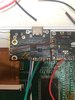
I've been having a strange problem with the PMS-PD drastically lowering the 3.3v rail resistance to GND. (And there is no way on EARTH that this is user error, as I've tried everything from re-wiring the joints, to taking it out and cleaning it. But if you really want to look at it, here it is:
image0 (1).jpeg)

Anyway, I've been trying to find a work around, and since I'm not using the 5V rail, I thought I could put it to use.

Using a 470K Ohm resistor, I managed to get the 5V rail to output around 3.3V. It kind of worked, but only if I connected it to the GC+, and connected the PD to that. But, for some reason, the GC+ was unresponsive if I did that.

The only solution left is to directly use the 5V rail, but I'm afraid that I may damage something if I do that. I only ask because I've heard that a lot of 3.3V components are 5V tolerant.


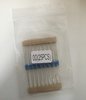
Also, TIL 0 Ohm resistors exist, and I own 25 of them.
image0.jpeg
 

dababy

.
Joined
Nov 7, 2021
Messages
110
Likes
40
I would do a bit more research and make sure even tho theoretically it would work because it’s no fun to blow out parts but it should work because standard USB ports run off 5v right? Idk I may be completely wrong but that’s my piece
 
Joined
Oct 22, 2021
Messages
38
Likes
17
Location
Canada
I would do a bit more research and make sure even tho theoretically it would work because it’s no fun to blow out parts but it should work because standard USB ports run off 5v right? Idk I may be completely wrong but that’s my piece
You are right that USB devices run off of 5V, but the 3.3v pin isn't for the USB. Analyzing the traces on the board makes me believe it's for determining if the PMS it's paired with is on or off, so it can switch the USB data lines to feed into the Wii, or to the USB C port accordingly.

That's why I think it might be able to work with 5V, since it must be just a matter of "high" or "low" voltage.

It'd really help if I could find the datasheet for component "U2", but unfortunately the part number is impossibly small to read.
 
Joined
Oct 22, 2021
Messages
38
Likes
17
Location
Canada
The answer is no. Rest in peace RVL-PD.

But round 2 with a voltage divider of 47 ohms for R1, and 100 ohms for R2 seems to work... for now.
 

Gman

RTFDS
Staff member
.
.
.
.
.
Joined
Feb 25, 2016
Messages
1,437
Likes
2,887
If there is low resistance from 3v3 to ground on the PD board then wouldnt it cause the same low resistance if you hooked up 5v to it?
 
Joined
Oct 22, 2021
Messages
38
Likes
17
Location
Canada
If there is low resistance from 3v3 to ground on the PD board then wouldnt it cause the same low resistance if you hooked up 5v to it?
The PD itself has the normal resistance to ground (9K Ohms I believe). But when I connect 3.3v it drops to around 5K ohms? The 5V line is completely unaffected, however.

I think there's something funky with the PMS lite itself, as the LED doesn't work, except for the split second when I unplug the charger, and the battery level is never right.

I'm planning on making a better portable when the PMS lite modules are back in stock anyway. (If you don't mind me asking, is that going to be relatively soon? Or is it also affected by the chip shortage?)
 

Gman

RTFDS
Staff member
.
.
.
.
.
Joined
Feb 25, 2016
Messages
1,437
Likes
2,887
There is a resistor on the pms pd 3v3. I dont see a problem here. If it is functioning, wire it as it is intended
 
Top