
Question can someone point out the main regulators on the board
- Thread starter wifflebat
- Start date
Unless a pro wants to point out where, I think your best bet would be to use the Wii Compendium to look up those spots.
Good luck!
Good luck!
- Joined
- Feb 25, 2016
- Messages
- 1,436
- Likes
- 2,876
Remove the large inductors and capacitors that are located outside of the OMGWTF trim. Also most importantly remove U18 and the 3.3v standby regulator. On the back, remove U15, U16, and U17. I usually just pull everything off with pliers and then use a soldering iron to clean up the connections so nothing has shorted.
Some boards you can get away with just removing U18, but others I have found it won't work so to be sure, you could just remove everything.
Some boards you can get away with just removing U18, but others I have found it won't work so to be sure, you could just remove everything.
- Joined
- Jan 31, 2016
- Messages
- 1,287
- Likes
- 2,726
- Portables
- 6
Here are the main onboard regulators. Remove all of these to run custom regulators.
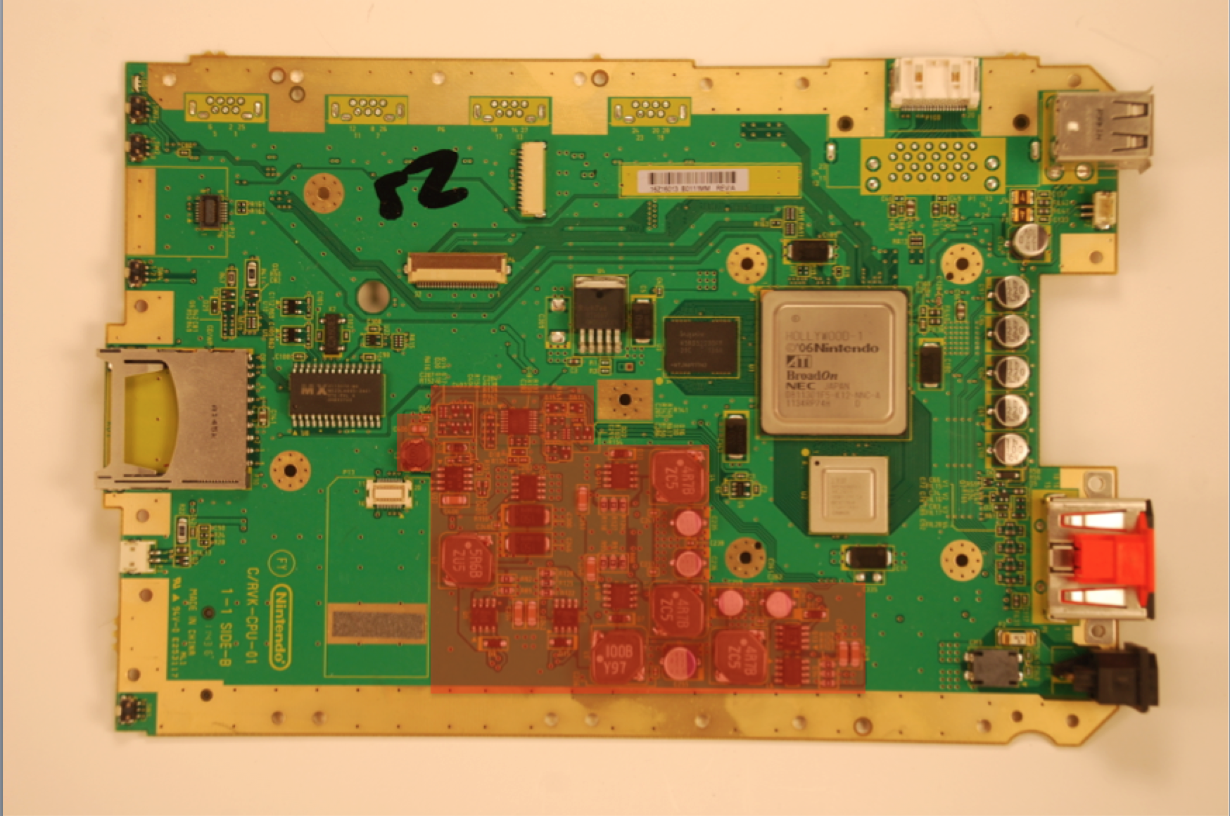
If you want to run custom regulators without trimming the board, it is highly recommended you remove every component within the red box. You will also need to connect both the 3.3v and 3.3v standby lines together and power them off of the 3.3v line.
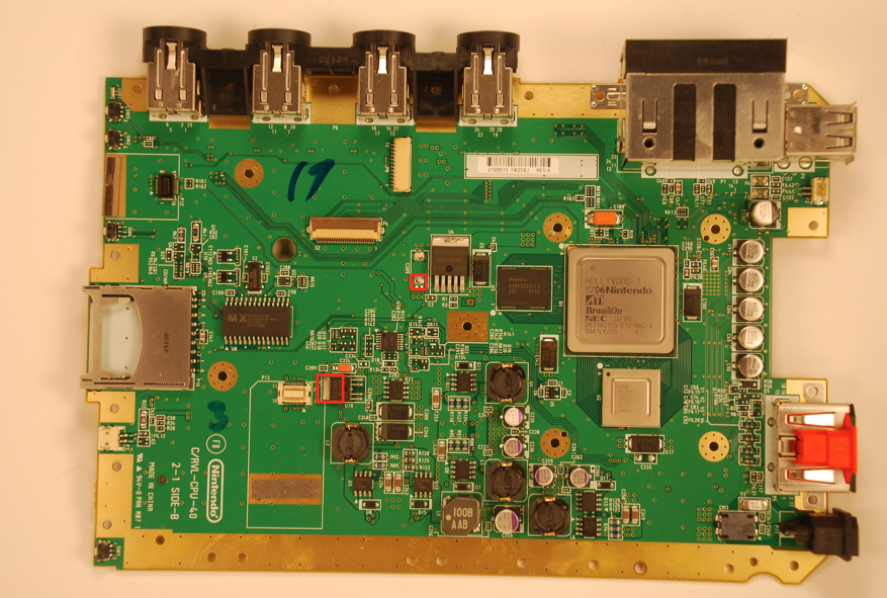
As for the standby line, all you need to do is to make sure it gets 3.3v power. You can do that by connecting the two voltage sections. Just run a wire connecting the two solder pads in the pictures below, run custom regs as normal and you are good to go.
Here are my prefered solder points for RVL-01, RVL-10, RVL-20, RVL-30 and RVL-40 boards
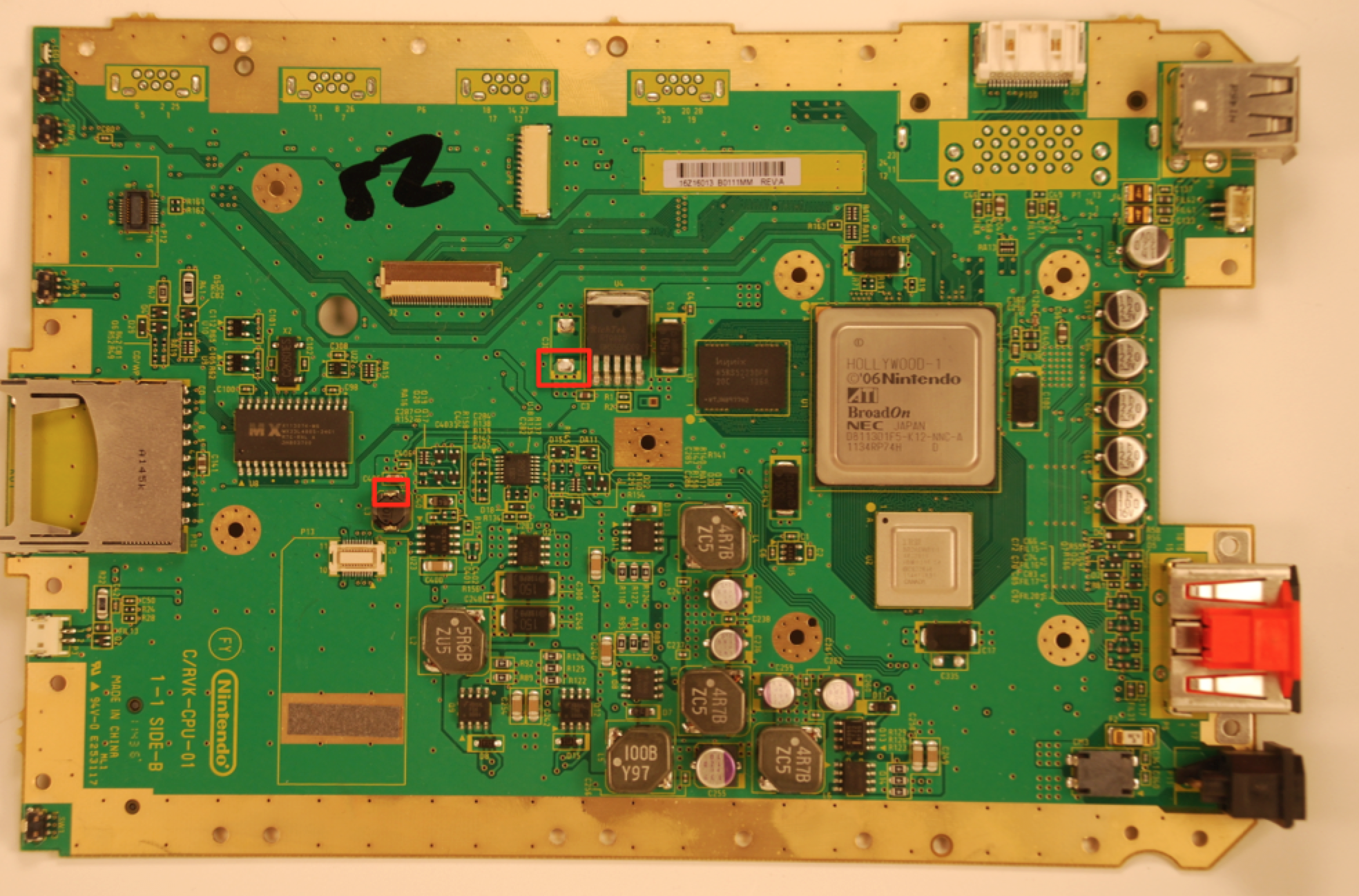
Here are my prefered solder points for RVL-50, RVL-60, RVK-01 and RVK-02 boards
Edit: Swapped a photo for a better quality one
If you want to run custom regulators without trimming the board, it is highly recommended you remove every component within the red box. You will also need to connect both the 3.3v and 3.3v standby lines together and power them off of the 3.3v line.
Which brings us to your second question: What is the 3.3v standby? The wii actually has TWO 3.3v voltage lines.
The 3.3v line powers the GPU, flash memory, gamecube controllers, sd cards and several other components that are used only while the console is on.
The 3.3v standby powers the MX chip, bluetooth module, and other components that still run while the console is off. This allowed the console to be booted wirelessly using the wii remote.
Why have you never heard of this before? For portablizing, it isn't really relevant. We don't need standby functionality and just power everything off of a single 3.3v regulator. The only thing you need to be concerned about is making sure you connect the two sections.
As for the standby line, all you need to do is to make sure it gets 3.3v power. You can do that by connecting the two voltage sections. Just run a wire connecting the two solder pads in the pictures below, run custom regs as normal and you are good to go.
Here are my prefered solder points for RVL-01, RVL-10, RVL-20, RVL-30 and RVL-40 boards
Here are my prefered solder points for RVL-50, RVL-60, RVK-01 and RVK-02 boards
Edit: Swapped a photo for a better quality one
Last edited: