Worklog Black G-Wii Rev 2 Worklog

cy

.
Joined
Sep 3, 2020
Messages
116
Likes
325
Portables
6
Per Gman's advice I'm starting a worklog for my second G-Wii. I decided to do it in GameCube indigo because I wanted it to look like a GC controller with a screen.

I started this project 2 days ago and I've come pretty far with it. So far I have the batteries, USB PD board, screen, screen controls, about 90% of audio, and yesterday I wired up the fan(I waited to do it until now because I was waiting for it to arrive).

Last night I did the necessary preparations for the ABY & X buttons and I also sanded the L R & Z buttons to make them fit in better with the glossy GC buttons. I started with 220 grit and sanded all the way up to 3000 grit and I think they turned out nicely!
20210723_212953.jpg

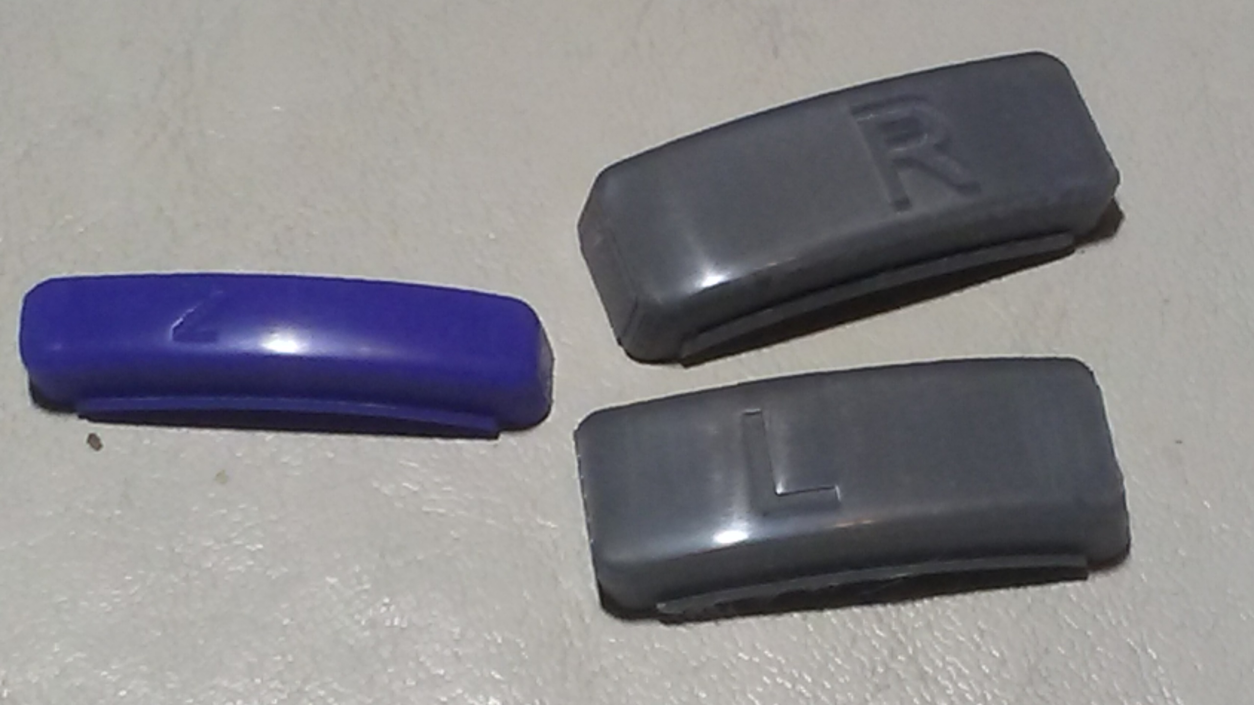
For a first honest attempt at sanding, I think I did pretty well. Shoutouts to Gman for sending me a shell to test sand, I was able to learn a lot from it and it helped me to get a nice final result as pictured!

Here's how the rest of the unit is turning out so far:
20210723_223648.jpg

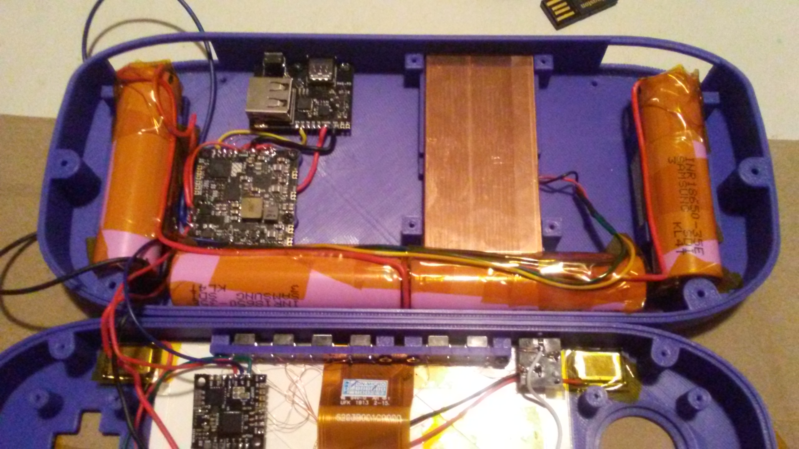
As you can tell by this image I've opted to disconnect the grounds so I can just hold them together for testing. This decision was made because I messed up my first PMS by briefly touching the positive and negative terminals.

Here's the other side. I learned a lot from my first time and I've managed to optimize the wiring quite a lot thanks again to Gman's advice!
20210723_223712.jpg

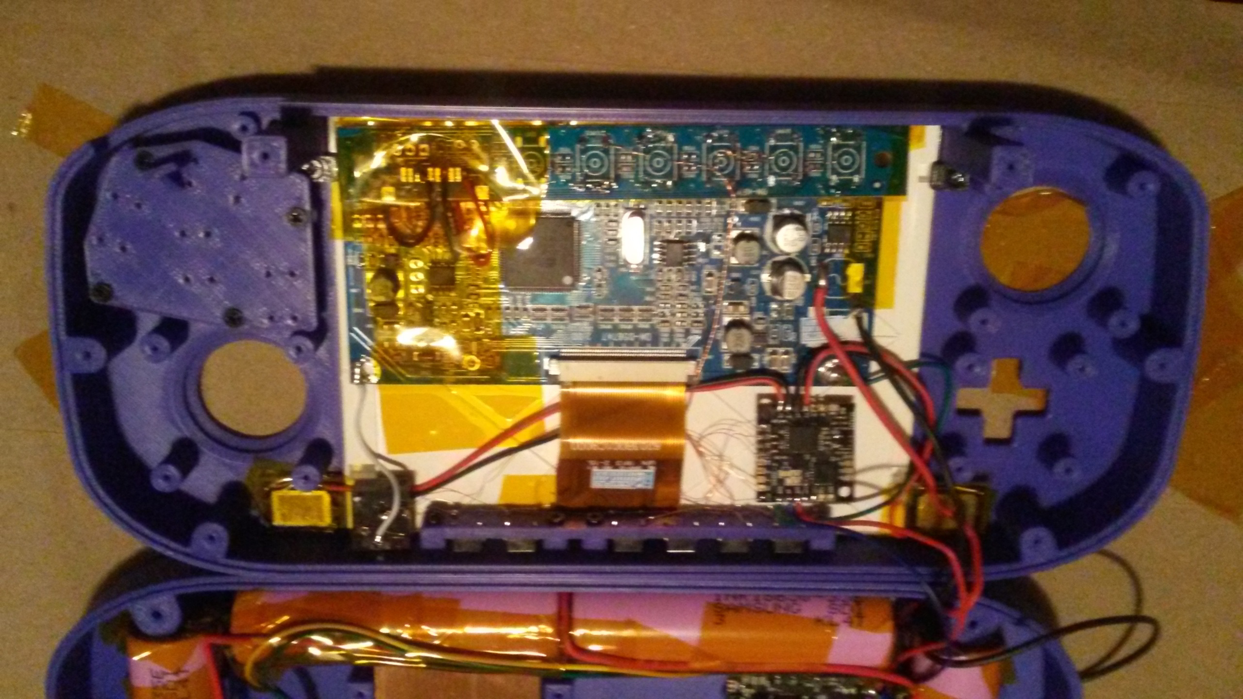
Not perfect but it won't be getting much worse since I'll be using magnet wire for most of what's left.

Next I need to set up my SD card file system for BBLoader as I have several trimmed wiis that already have BBLoader on them. I'm not planning on introducing the motherboard until everything is ready to be wired up to it.

I'm choosing to do this for several reasons:

First off, I'd rather not screw down the board multiple times.

Second off, the board tends to get in the way, and having to hold up the board in order to solder is never a fun time.

Third off, I can make the motherboard my main focus and start adding things to it one after another without needing to do something else on the side. Things will just be easier this way as I'll end up knocking fewer wires loose *cough* USB data lines *cough*.


Feel free to leave your thoughts on my work thus far! I've never created a worklog before so feel free to criticize my formating as well!
 
Last edited:

cy

.
Joined
Sep 3, 2020
Messages
116
Likes
325
Portables
6
Today I wired up and mounted one of my trimmed Wiis. I'm still waiting on some grey squishy tacts for the rest of the controls since I have basically everything else done at this point. Here's how that turned out:
20210725_221416.jpg

Pardon the unconventional trim, these things happen sometimes. What matters is it works!
Now would be a good time to mention I decided to wire up bluetooth for this portable! This was my first time doing it, but it ended up going just as smoothly as the rest of this build has. Here's what that looks like:
20210725_221344.jpg

I put Kapton tape over the NAND before I taped it down. Kapton tape doesn't tend to come loose from my experience and I prefer it to hot glue even if it doesn't turn out as clean. Here's an pic I took to show bluetooth works:
20210725_202626.jpg

I'm happy with the progress I made today even if it wasn't all that much. All I really have left at this point is controls, VGA, USB Data lines, Audio, and I wouldn't be caught dead without the MX Chip. I've decided for this build I'll also be skipping the RGB LED as it's not really useful anymore and I have decided I'll be using the hole that the RGB LED as a place to put an extra button for syncing Wii remotes.
 

cy

.
Joined
Sep 3, 2020
Messages
116
Likes
325
Portables
6
Alrighty so update time. I've essentially finished the unit, (wired up controls, audio, MX etc) and I've even closed it and fully charged it. For some reason, the Wii is losing power after a few seconds of turning the unit on now. I've looked inside and nothing looks loose/bridged. I'm thinking it could be that I used magnet wire to power the GC+2.0 and Bluetooth, though I'm not certain. I'm posting here asking because I'd like to know if I'm looking in the right place before I tackle it and I'd also like to hear any other ideas you guys have. At this point, that's my only real lead, and I kinda doubt that'll fix it. Here's what the internals are looking like:

Resized_20210801_015201.jpg

Resized_20210801_015216.jpg

Not sure how helpful it is, but I will say compared to last build, I'm very happy with how much cleaner this one turned out if nothing else. If only it worked haha.
 

Gman

RTFDS
Staff member
.
.
.
.
.
Joined
Feb 25, 2016
Messages
1,436
Likes
2,876
Make sure the batteries are charged! No wiring magnet wire on the gc+ and bt is not an issue
 

cy

.
Joined
Sep 3, 2020
Messages
116
Likes
325
Portables
6
Update: Looks like I had a short on the 3.3 volt rail. Thanks so much again for all the help Gman! I'll be taking/posting pictures here once I verify it's more stable.
 
Joined
Jul 9, 2020
Messages
227
Likes
498
Amazing and inspiring! I’m about to start mine too… just waiting for the last of the parts to arrive from Ali express.

I love the idea for the Wiimote sync button rather than the LED. Nighttime sessions are also blinding with that LED in my experience too.

I’m also curious why you bridged C 90 and C 56 with that magnet wire.…?

Great job dude! Well done…
 

cy

.
Joined
Sep 3, 2020
Messages
116
Likes
325
Portables
6
Amazing and inspiring! I’m about to start mine too… just waiting for the last of the parts to arrive from Ali express.

I love the idea for the Wiimote sync button rather than the LED. Nighttime sessions are also blinding with that LED in my experience too.

I’m also curious why you bridged C 90 and C 56 with that magnet wire.…?

Great job dude! Well done…
I had to re-solder that resister and the ground pad had lifted when I accidentally removed it when I was working on the board a while back. Basically that's my way of re-attaching ground to that resister.

I already asked this question in the discord but I suppose I'll ask here as well. I've got everything back up and running stably except for this one issue

Here's what my GC+ data line is looking like on both ends:
2.jpg
1.jpg

Everything else has been fine as previously stated. Anyone have any ideas? I didn't notice this issue until I re-wired the U-Amp. Thanks!
 
Last edited by a moderator:

cy

.
Joined
Sep 3, 2020
Messages
116
Likes
325
Portables
6
Why did you remove RA1? there's your issue!!
It's a long story. Basically Noah told me that he had a bad one on one of his Wiis back when I was working on a separate project. This motherboard is a leftover attempt to replace RA1 on a different board which ended up not working because it was the PMS on that build all along. I seem to have somewhat stable results for now though I may look further into it if I run into future issues. Thanks for the help!

Edit:
I have gotten somewhat stable results with RA1 removed before. Routing and other things become a nightmare with it gone though.
 

Stitches

2 and a Half Dollarydoos
Staff member
.
.
Joined
Feb 5, 2017
Messages
3,812
Likes
3,004
Location
Banana Bender Land, Australia
Portables
6
Pull-up resistor array, right? Or is it a filter array?
 

StonedEdge

a.k.a. ClonedEdge
.
.
Joined
Nov 16, 2018
Messages
363
Likes
1,487
Location
Japan, Tokyo
Portables
2
Pull-up resistor array, right? Or is it a filter array?
Pretty sure that resistor array pulls each GC controller data line to 3v3. Without it your GC data line is floating and won't work
 

Gman

RTFDS
Staff member
.
.
.
.
.
Joined
Feb 25, 2016
Messages
1,436
Likes
2,876
RA1 is a 750 ohm resistor array on each GC data line. It is absolutely necessary. You can add a 750 ohm resistor from GC data to 3.3v on the GC+. RA1 won't just randomly "die" , the only way it could break is if you solder to it and damage it.
 

cy

.
Joined
Sep 3, 2020
Messages
116
Likes
325
Portables
6
RA1 is a 750 ohm resistor array on each GC data line. It is absolutely necessary. You can add a 750 ohm resistor from GC data to 3.3v on the GC+. RA1 won't just randomly "die" , the only way it could break is if you solder to it and damage it.
Per Gunnar's advice I've ordered some 750 ohm resistors as I have other motherboards missing this component. I've closed this unit and tested the battery life on it. I've gotten 3 hours and 45 minutes on my first test with a second test currently in progress. The unit has been on for around 2 hours now and the temp has maximized at 56C. Everything except controls have proven to be stable with the controls failing on me once. I fully plan on re-opening this once the resistors I ordered arrive, however I do think verifying stability and testing the battery life in the meantime was a good idea. Things have been holding up well otherwise!

Edit: I forgot to mention, I did a power calculation and I ended up with 9.07386 Watts of power draw, sounds normal according to Gman. Not sure if the batteries I ordered are just sub-par but I may take a closer look at things if I continue to see these lower end battery life results for the sake of safety.

Edit 2: I will also take new pics of the internals and post them before I close the unit back up for a final time so yall can see the work I've done.
 

cy

.
Joined
Sep 3, 2020
Messages
116
Likes
325
Portables
6
Update:
So I've spent the past week+ testing this unit, and out of nowhere it just started freezing randomly and giving me disk errors on games. It wasn't at all consistent and would sometimes happen on the RVLoader screen as soon as the RVLoader logo got displayed as well as mid-game session. Sometimes it was just a disk error, other times the music and misc elements that need to be loaded would just fail.

All signs pointed to it being the data lines for USB, so today I re-did the USB data lines completely. I made sure to twist the wires tighter and I ensured the solder joints were solid. Unfortunately, I continued to run into issues even after mindfully routing everything to avoid interference. It's quite possible my data lines were loose as the disk errors appear to be gone. Unfortunately though, the unit hasn't stopped freezing.

I happen to know if you remove bluetooth from an untrimmed Wii while it's turned on, the unit will freeze even if you have RVLoader installed. I decided to remove bluetooth from this unit to see if it could be my solder joints, bluetooth does require soldering to two 0.1 mm traces after all. So far after closing the unit and removing bluetooth, I'm yet to run into any issues. I'll continue to test extensively and eventually once I'm comfortable the unit is stable, I'll post images of the internals and games running on it. I'd like to get this thing truly finished before I just post pics and call it "finished". Barring any stupidity that shouldn't take too long.
 
Joined
Jul 9, 2020
Messages
227
Likes
498
Good troubleshooting mate! Glad it’s not freezing now.

I am curious to see the Bluetooth data solder joints. How did you expose the traces? I had issues with that in the past... I think for the next build I’m going to locate a fiberglass pencil to make a really clean de-mask point for each line. Maybe you could try that too.

Do you have photos of the joints from when it was freezing?

Did you probe around on Bluetooth unit to make sure voltage lines were securely soldered?

It’s always so interesting to me when new problems come up, finding solutions together to make future builds more flawless is compelling and I love the process..

thanks for posting :)
 

cy

.
Joined
Sep 3, 2020
Messages
116
Likes
325
Portables
6
Good troubleshooting mate! Glad it’s not freezing now.

I am curious to see the Bluetooth data solder joints. How did you expose the traces? I had issues with that in the past... I think for the next build I’m going to locate a fiberglass pencil to make a really clean de-mask point for each line. Maybe you could try that too.

Do you have photos of the joints from when it was freezing?

Did you probe around on Bluetooth unit to make sure voltage lines were securely soldered?

It’s always so interesting to me when new problems come up, finding solutions together to make future builds more flawless is compelling and I love the process..

thanks for posting :)
I did probe the voltages and I was careful to ensure ground and 3.3volts didn't bridge.

I'm still not certain that my solder joints from bluetooth were causing it to freeze, but I've done like an hour and a half of testing games and I haven't seen it happen again. If bluetooth didn't require lifting the motherboard and it weren't an incredible pain in the ass, I'd fix it. But it's not a feature I consider to be worth while, it's just one more thing to troubleshoot that could also come loose at the end of the day.

I just use my multi-meter probes to scrape vias/traces, it works really well just make sure you don't scrape too hard!

And no, I don't have photos, didn't think to take them when I removed the wires, sorry.
 

cy

.
Joined
Sep 3, 2020
Messages
116
Likes
325
Portables
6
It's been a bit since I've posted an update so I'll do just that. It turns out my issue with freezing/crashes wasn't bluetooth, and it wasn't USB lines, reformatting the micro SD card didn't do me any good either. I'm still not at all sure what the problem could possibly be, at this point, I've had to fix things that have come loose so many times that I know I'm just best off re-building the unit. That said, I'll be using a different USB-C board to see if I get the same results I had last time. If I don't run into any more freezing, and if I run into this problem next project, I'm gonna assume it's the board(wouldn't be the first time I've had USB-C board problems this project). I'll keep everyone posted with the progress I make as I make it, currently I'm working on sanding the shell because I wasn't happy with how it felt when it was mostly assembled and finished. I will post pics of my sanding work once I'm happy with my results.
 

cy

.
Joined
Sep 3, 2020
Messages
116
Likes
325
Portables
6
Alrighty, so this was originally intended to be an Indigo G-Wii but things happened and plans changed. It is now a galaxy black G-Wii. That said, I've been having the strangest loading issue for a while now(see the video I posted).

It has happened across multiple Wii motherboards. I've had issues with the game crashing randomly with the same setup on a different motherboard. I've twisted my magnet wires VERY tightly and carefully routed them(I've tried looser twisted magnet wire for my data lines too). I've also tried formatting the micro SD card, swapping out the adapter, and swapping out the USB-C board entirely. It occasionally effects loading times, I'm yet to have it fully crash on the past two motherboards. So it's possible that it's just a performance issue, but this is a G-Wii with the classic G-Wii cooling solution(with thermal paste). Furthermore, it has happened when the unit hadn't warmed up yet, so I'm at a total loss here.

Edit: It's worth mentioning that since I've swapped out the motherboard(for a third time in an attempt to figure out what's going on), I've not wired up audio, VGA, or the MX Chip. I only have the absolute necessities wired up until I get stuff like this ironed out(per Gman's advice).
 
Top