
don't throw the board away, hold onto it for a future project once you can trouble shoot it when you have more experience with portablizing, or you could see if an experienced member could use the board rather then just letting the board go to wasteHi,
I’m back to having no signal output.
I’ve redone the U10, changed the voltage wires and removed components outside of the trim.
At this point I’ve decided to get another Wii, since they are cheap (around $15 where I am) and I will hopefully do it better this time. Doing the U10 first and testing that before the trimming process.")
Worklog Beginner Project - The Wii ToU
- Thread starter TropicPug
- Start date
-
- Tags
- nintendo wii wii portable
Ok then, I’ll keep it and hopefully it’ll find a use in the future.
An update, I trimmed and wired up a second board and it works! Boots into the post loader error screen! Feels amazing to finally have a working board.
I have also decided to change my project from a Wii u gamepad to a G-Wii design. This means it will be much easier to complete and I can ensure that the console will have a working cooling solution and be much neater and less prone to errors that trying to jam everything in a Wii-U gamepad with 3D printed supports.
I can then use what I’ve learnt at a later stage for a more complex project like a fitting everything into a Wii-U gamepad or designing a custom shell.
The plan for the next steps is to get the case printed and then begin wiring up USB and everything else to get everything working as well as desoldering components from the main board I plan to use such as the memory card slot.
And I’m back!
Been pretty busy during COVID and finally found the time to sit down again and get the modding going!
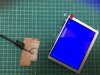
Given my switch to now making a G-Wii rather than a Wii U shelled portable, Ive had to change the LCD.
I’ve decided to use a ZJ050NA-08C, and I’ve modified it to work with 5V.
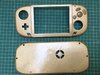
I also resin cast myself some buttons and 3D printed the shell and painted it gold and used some toy safe clear coat to ensure the paint shouldn’t chip on so easily.
Hoping to get the cooling system sorted as well as the cell charging system in place soon.
Been pretty busy during COVID and finally found the time to sit down again and get the modding going!
Given my switch to now making a G-Wii rather than a Wii U shelled portable, Ive had to change the LCD.
I’ve decided to use a ZJ050NA-08C, and I’ve modified it to work with 5V.
I also resin cast myself some buttons and 3D printed the shell and painted it gold and used some toy safe clear coat to ensure the paint shouldn’t chip on so easily.
Hoping to get the cooling system sorted as well as the cell charging system in place soon.
Attachments
-
 2.3 MB Views: 214
 -
 2.3 MB Views: 254
Back and found a new problem!
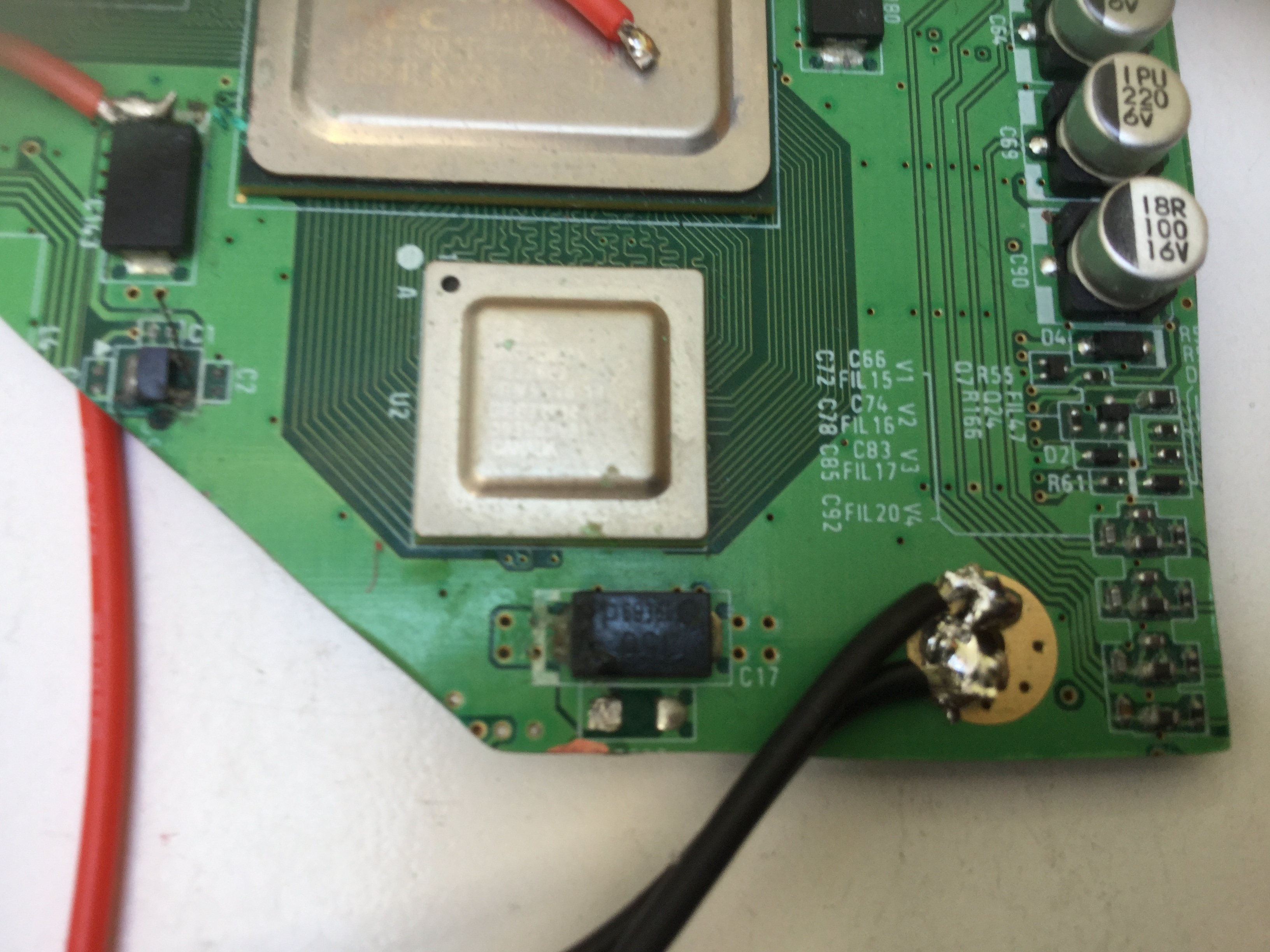
My previously working wii trim (after now connecting to an RVL PMS rather than a PTH08080 regulator setup), has ceased to work.
I have identified the issue to be a short on the 1.15V line to ground.
The short is to both 1.15v pins.
From the image, I think the issue may be the small piece of exposed copper at the bottom?
Could I Sever the connection between the two 1.15V input points and wire 1.15V in to the left side of the rectangular chip (stopping the short perhaps?).
Got the motherboard working!
Turns out there was some dust on the board (that was likely causing a short).
I cleaned below the GPU and CPU and found quite a lot of dirty, so it wouldn’t suprised me if that was where the issue was.
This was likely due to me not taping over these chips when I trimmed the board (BIG MISTAKE, I’ll add this to my what not to do list).
I have sadly found that my trim doesn’t fit into my G Wii shell! I’m going to need to trim the board down again, wish me luck!
Hi all!
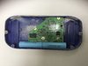
Realised that the Wii was too large to fit inside the shell, so I needed to trim it again. Went through the process of sanding and trimming and got it booting, and now it fits in the case.
This is because, unbeknownst to me, the G Wii requires a smaller trim than the normal OMGWTF trim (you can find this on the forums).
All I’ve got left now is assembling the heatsink, then I’ll be ready for the final assembly
Attachments
-
 2.1 MB Views: 218