
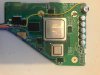
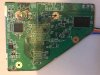
3.3v and 5v are relatively high resistance to gnd, 1v is typically above 100 ohms and 1.15v is typically 25-50 ohmsHuge update! Hello everyone, I've slowly been amassing parts and knowledge to continue on with my WII portable and today I finally cut my motherboard! I think it went pretty well. Before hooking it up to my regulators I was wondering what resistances I should expect between the various voltage lines and ground? I've checked the other sources and I think this information could be helpful as a post on the Guide Hub. Here are the pictures of my update, I've also started the case design and will be modeling my portable after the GameBoy Advanced! I know I still have a lot of work to do, I still need to sand the sides of the board and remove the video port, the usb ports, and the Hot Glue but its getting there!
View attachment 7363
View attachment 7364
Worklog Bayjose's Wii Portable
- Thread starter bayjose
- Start date
bayjose
.
- Joined
- Oct 9, 2017
- Messages
- 45
- Likes
- 11
Thank you so much!3.3v and 5v are relatively high resistance to gnd, 1v is typically above 100 ohms and 1.15v is typically 25-50 ohms
bayjose
.
- Joined
- Oct 9, 2017
- Messages
- 45
- Likes
- 11
Did some additional sanding! and... it works! it dosent always boot up right away, and sometimes i get erros loading the menu and it will boot into homebrew. I think this is related to line voltages though, the 1.0V line is down around .89V at times, and the 1.15V line goes down to about 1.0V. Im going to get some potentiometers to try to tune the resistances to get the perfect output voltages, then measure the pots to replicate that exact resistance.
Feel free to leave any comments or ask any questions! I love this community and I have learned so much from all of you. Having a portable GameCube has been a dream of mine for around 8 years now, and I feel like things are finally coming together!
Feel free to leave any comments or ask any questions! I love this community and I have learned so much from all of you. Having a portable GameCube has been a dream of mine for around 8 years now, and I feel like things are finally coming together!
bayjose
.
- Joined
- Oct 9, 2017
- Messages
- 45
- Likes
- 11
I have been reading forum posts about what sorts of resistances to expect between each line and ground and I think that my resistances are okay.
1.0V - 102
1.15V - 39
3.3V - ~19K
5V - super high
I need to get some potentiometers to tune my regulators to output the correct voltage. They are spot on when not connected to the board, however when they are connected to the wii I am getting the following voltages on each line.
1.0V - .89V
1.15V - 1.00V
3.3V - 2.97V
5V - 4.79V
If anyone wants to look at my trim up close here are some pictures. Should I be worried about these low voltages? Maybe my caps are bad? I only intend to use the pots i'm ordering to determine the nominal resistance of the board, then Ill get some 1% resistors to match that exact resistance. Dose that sound like a good plan? I would really applicate any input")
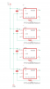
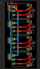
ALSO I have been trying to teach myself some PCB design in eagle. I have designed a little board to hold my PTH08080 regulators, with some nifty places for capacitors and resistors. I know its pretty minimal but i'm proud of it
1.0V - 102
1.15V - 39
3.3V - ~19K
5V - super high
I need to get some potentiometers to tune my regulators to output the correct voltage. They are spot on when not connected to the board, however when they are connected to the wii I am getting the following voltages on each line.
1.0V - .89V
1.15V - 1.00V
3.3V - 2.97V
5V - 4.79V
If anyone wants to look at my trim up close here are some pictures. Should I be worried about these low voltages? Maybe my caps are bad? I only intend to use the pots i'm ordering to determine the nominal resistance of the board, then Ill get some 1% resistors to match that exact resistance. Dose that sound like a good plan? I would really applicate any input
ALSO I have been trying to teach myself some PCB design in eagle. I have designed a little board to hold my PTH08080 regulators, with some nifty places for capacitors and resistors. I know its pretty minimal but i'm proud of it
- Joined
- Dec 10, 2016
- Messages
- 578
- Likes
- 663
- Location
- Constant Fear
- Portables
- sin^2(x) + cos^2(x) +e^(i*pi)
ayyyy, Eagle too
if you plan to invest in a heat gun(or have one), I'd suggest looking into better regulator options, because PTH expensive than alot of regulators that are better.
if you plan to invest in a heat gun(or have one), I'd suggest looking into better regulator options, because PTH expensive than alot of regulators that are better.
bayjose
.
- Joined
- Oct 9, 2017
- Messages
- 45
- Likes
- 11
I actually already have the regulators, in the future I do want to look into alternative voltage regulator sources though because yeah, those regulators cost more than the wii did xD Do you have recommendations? I think it would be cool to use some smd components and make a small all in one board that would have power in, a connection for a power switch, a 2 cell BMS and the wii voltage outputs, 1.0, 1.15, 3.3, and 5. Basically replace the red board that lots of people use and the regulators with something compact.
- Joined
- Dec 10, 2016
- Messages
- 578
- Likes
- 663
- Location
- Constant Fear
- Portables
- sin^2(x) + cos^2(x) +e^(i*pi)
lots of people have been using the http://www.ti.com/lit/ds/symlink/tlv62130.pdf
I think it's what the Powermii lite uses iirc
I think it's what the Powermii lite uses iirc