Worklog Ashida Worklog + Questions

Joined
Feb 12, 2023
Messages
9
Likes
20
Location
CA
Portables
1
After years of modding Gameboys and staring longingly at portabilized consoles, I've decided to take the plunge and build an Ashida for myself. I've spent the past weeks reading the forums and gathering parts, and I've already put a significant dent into things, though the hard work is all ahead of me. I meant to start a worklog when I began putting together the 4layer boards, but got too excited and forgot to take pictures. Instead we'll start this log with most of the front shell and a good chunk of the back half populated with boards and wires. By the end of this I'll be able to play my Gameboy on the big screen and GameCube on the couch, exactly as Nintended.


First off, the shell! I ordered a UTR Imagine Black resin shell from PCBway, just to keep things simple. For buttons, I harvested an OEM Indigo controller I got at a thrift store for $5 with a broken b button, plus an extra aftermarket z to go on the left. I'll need to trim the z buttons even more than I already have (especially the aftermarket one, which seems to be a bit thicker than OEM) for things to play nicely when buttoned up.


Screenshot 2023-02-22 at 4.46.47 PM.png


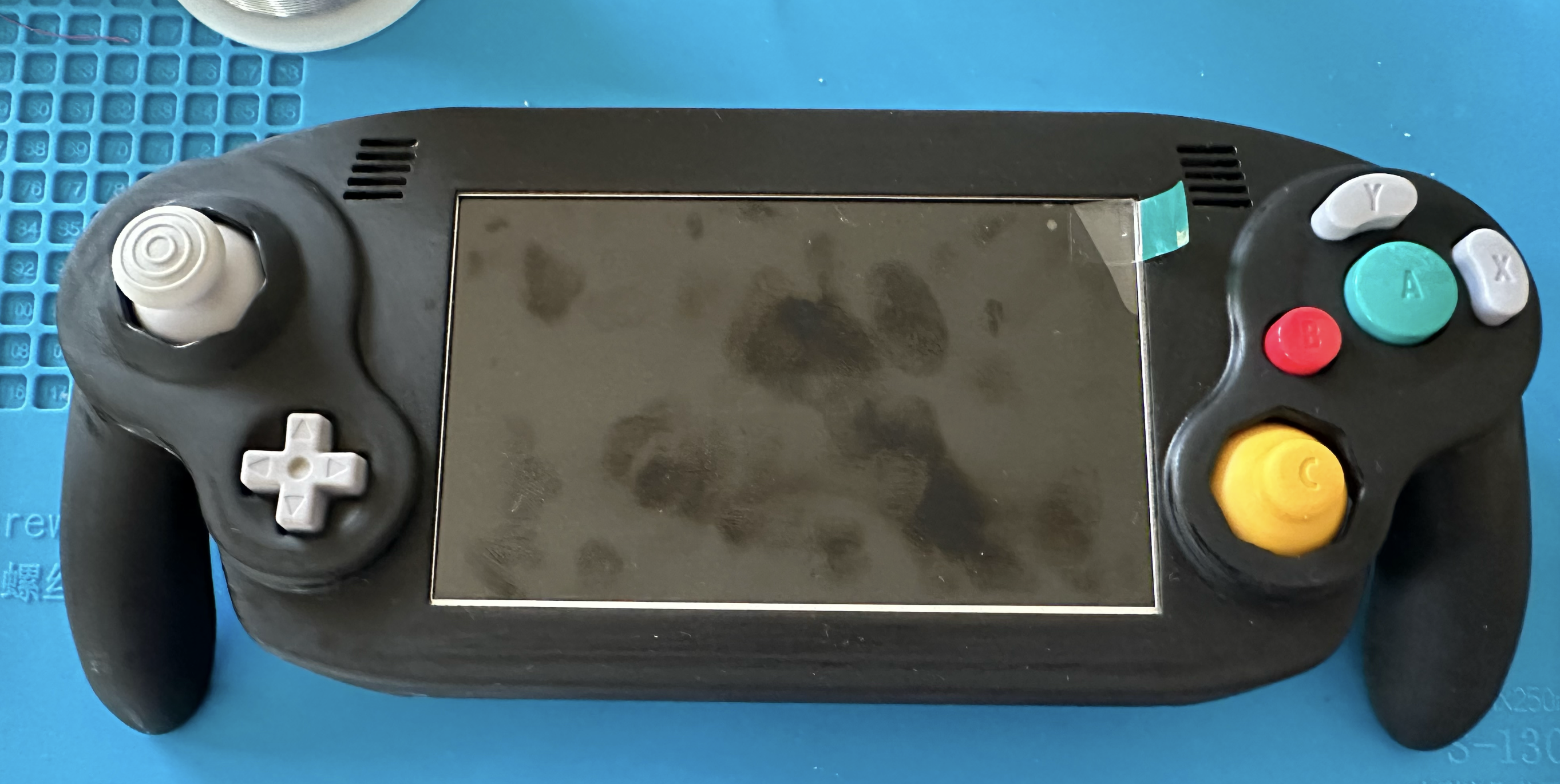
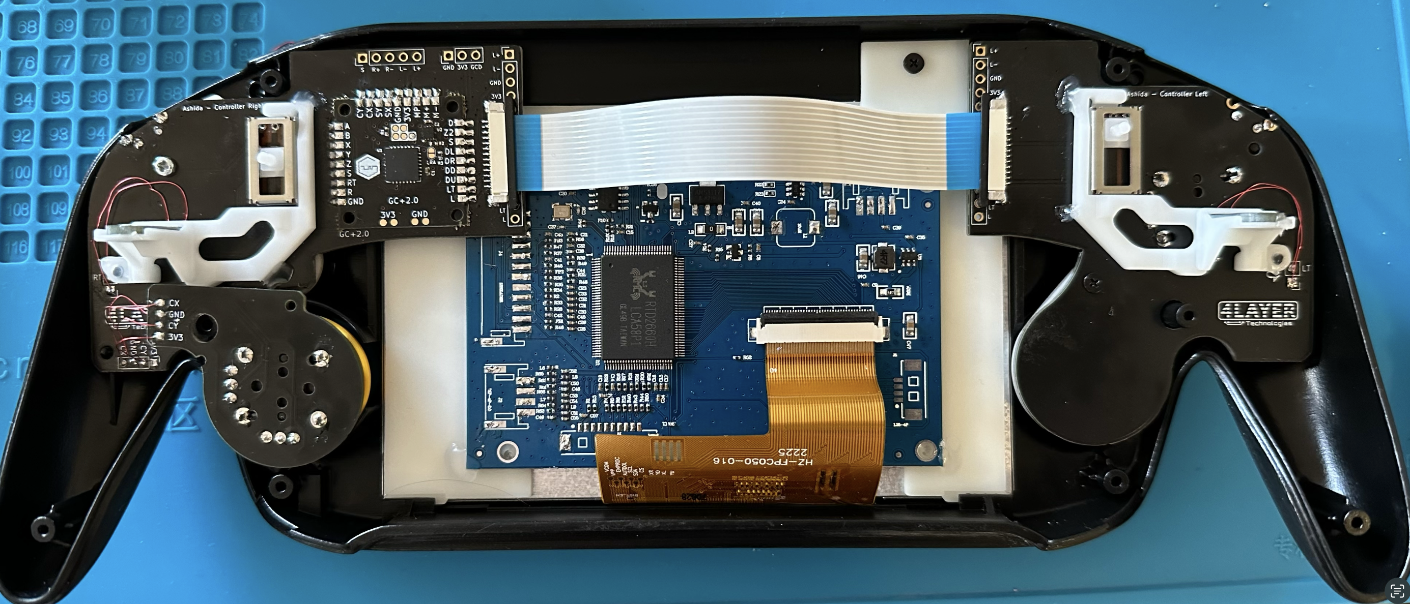
The inside of the front shell is already populated with the 4layer controller boards, GC+2, IPS screen +driver board and is essentially complete besides the wires from the driver board that I'll do later when I begin to connect the two halves. The 3D print for the driver board aligner didn't play nicely with my 5mm screws except at the top for some reason, so the board is held in place with a bit of hot glue, which I feel slightly "eh" about. The only thing that gave me trouble about this half was actually the c-stick board. I had attempted to use the connector that come directly off the OEM board, but the plastic connector was much too thick to close the Ashida shell afterwards, and it was a pain to desolder since all four pins were rigid. I highly recommend just using magnet wire here unless you have something very flexible.


Screenshot 2023-02-22 at 4.47.05 PM.png


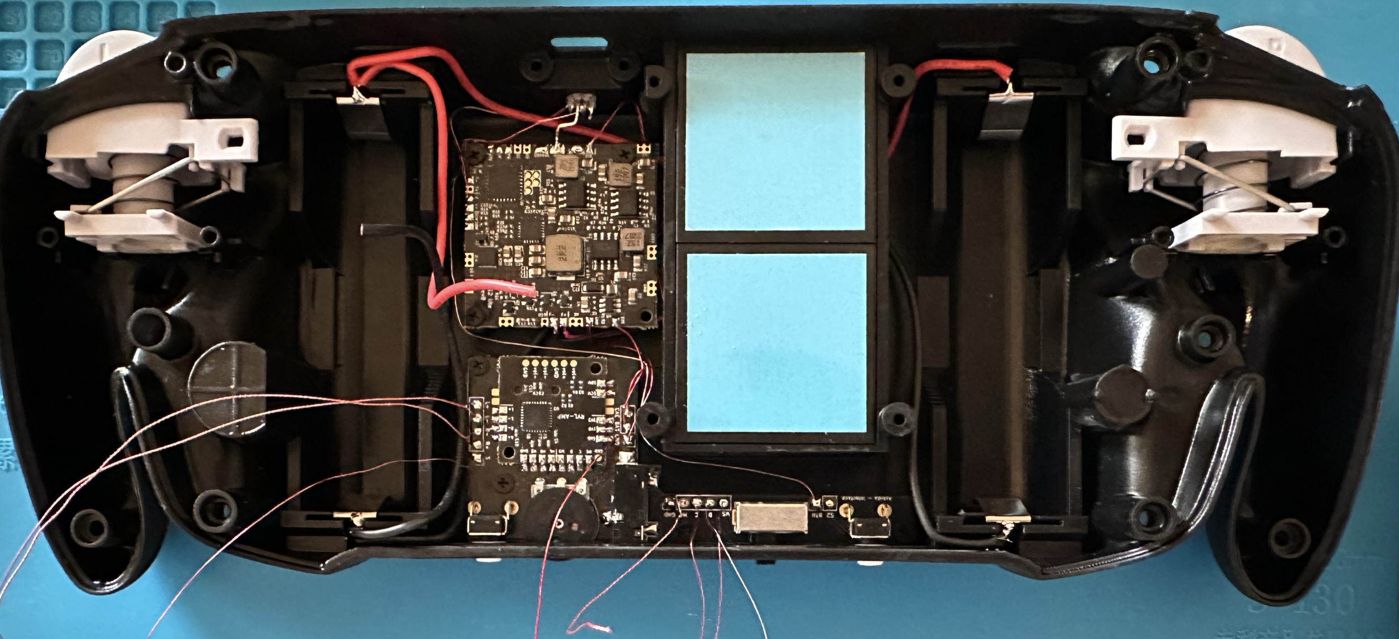
The back half of the shell is in-progress. I have the audio board (with RVL-amp) plus the PMS2-lite screwed in and mostly connected, though I still need wires for SCW/SDW and headphone sense before I start working with the Wii. My next steps are to wire in the PMS-PD 2 and the Wii itself. I've been delayed on this because the PD2 was out of stock, and when it finally came in, my drive didn't fit! PSA: Samsung Fit and SanDisk Ultra Fit are not close enough in dimension. Fortunately I was able to use the Samsung USB to mod the wii and install rvloader v1.6, so I'll just transfer the files over the new drive after reformatting.


Screenshot 2023-02-22 at 4.47.42 PM.png


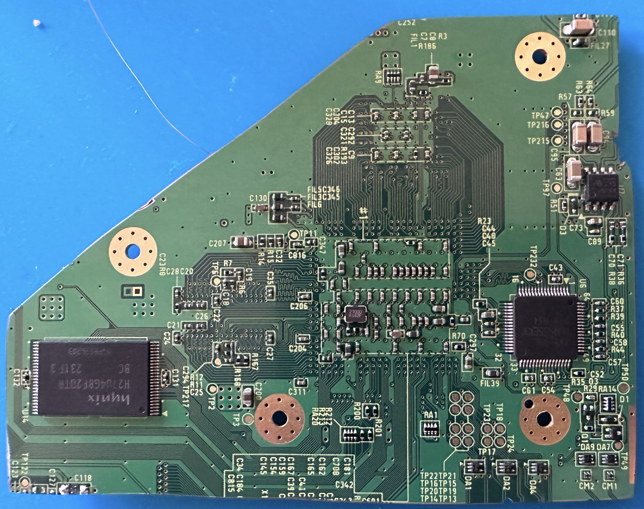
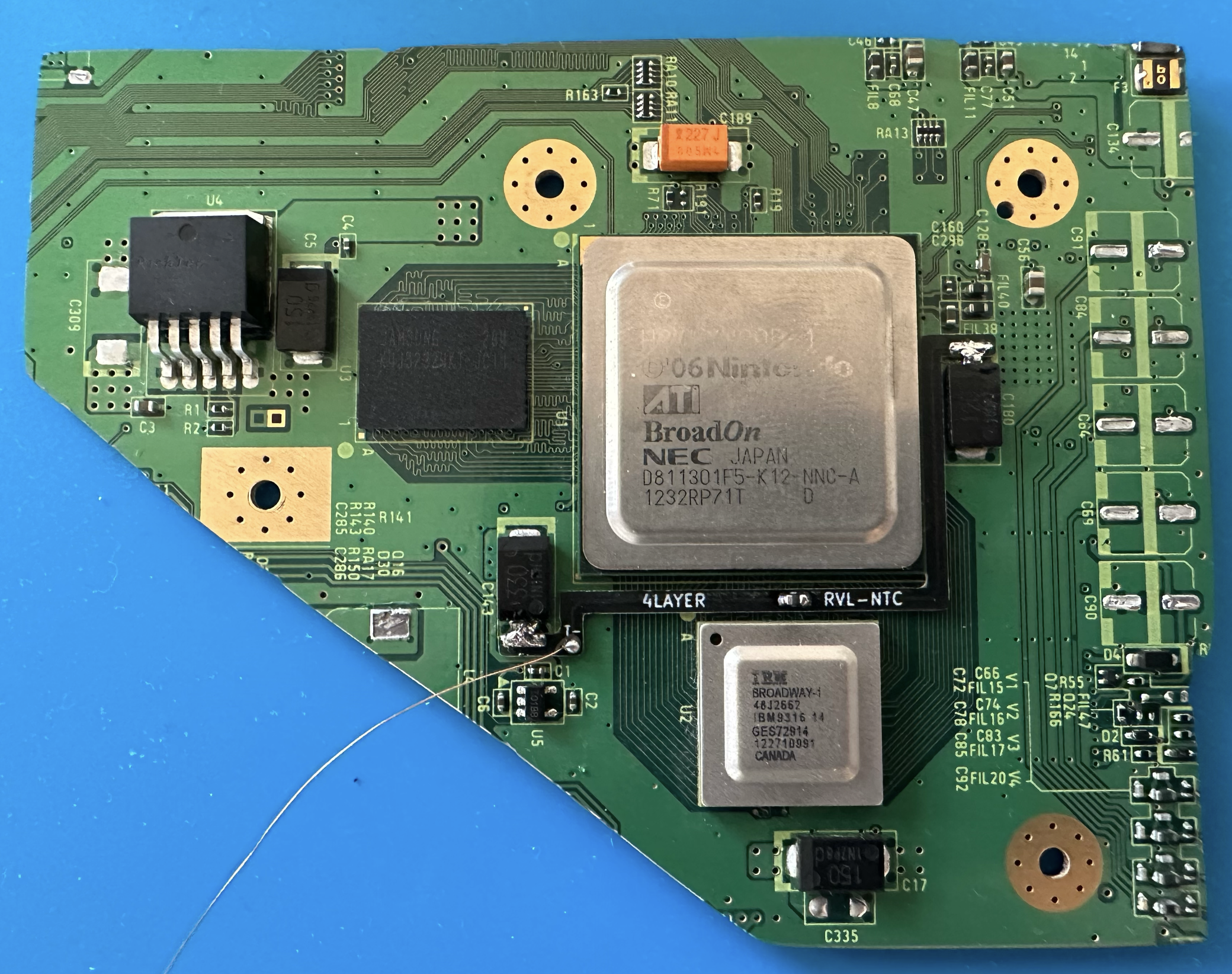
As for the Wii itself, I did my first Wii trim! The OMGWTF trim definitely made me vocalize the eponymous acronym when I first saw it, but honestly it was very straightforward. After taking a diamond cutting wheel to an RVK-CPU-02 board and sanding for a while, I have what seems to be a usable board based on trim resistances. These Wii vias are pretty small and intimidating (definitely smaller than Gameboys), so I'll probably solder some wires to the vias on the discarded Wii board first to get some practice.


Screenshot 2023-02-22 at 4.46.28 PM.png
Screenshot 2023-02-22 at 4.46.36 PM.png


That does it for my progress so far! Most of the work left is on the Wii itself, but I'm getting there! I mostly have time to work on the weekends, but I'm hoping to finish over the next couple of weeks.

A few questions as I move on to next steps:

  1. I see lots of comments for not to get USB +/- confused from the PD2, but which lines coming off of CM1/2 are are actually +/-? I don't see that in the definitive trim guide.
  2. I twisted MC and Ground for the audio wires to the Wii, but what is the best/closest ground plane/via to MC? There isn't a large ground plane fairly close and I feel unwrapping the wire to reach one defeats the purpose.
  3. I did not do an MX or bluetooth relocation for this first portable, so the right button on the bottom shell is currently unused. Are there any fun/interesting things I could repurpose it for without unscrewing the 4layer board?
 

Stitches

2 and a Half Dollarydoos
Staff member
.
.
Joined
Feb 5, 2017
Messages
3,817
Likes
3,011
Location
Banana Bender Land, Australia
Portables
6
A few questions as I move on to next steps:

  1. I see lots of comments for not to get USB +/- confused from the PD2, but which lines coming off of CM1/2 are are actually +/-? I don't see that in the definitive trim guide.
  2. I twisted MC and Ground for the audio wires to the Wii, but what is the best/closest ground plane/via to MC? There isn't a large ground plane fairly close and I feel unwrapping the wire to reach one defeats the purpose.
  3. I did not do an MX or bluetooth relocation for this first portable, so the right button on the bottom shell is currently unused. Are there any fun/interesting things I could repurpose it for without unscrewing the 4layer board?
Answers ahoy!
  1. The USB lines marked in green are D+ and the grey lines are D-. This isn't expressly stated in the trimming guide, but it follows general electrical legend convention that in any given circuit: positive is shown as a bright colour, and negative is a dull colour like black/grey/white/washed out version of the positive colour. That should probably be stated outright in the guide, I'll edit it later to resolve that. In the meantime, here's a pretty snip from the G-Boy manual to illustrate:
    1677136911725.png

    Make sure to use CM1 first, as the Wii typically works best with slot 0 (the first slot is marked in software as 0 rather than 1, so slot 0 is CM1)
  2. I believe these vias are ground vias:
    1677137315469.png

    I don't have a board handy to double check this tho, so I'd check with a multimeter on your board first to ensure they have true continuity with ground.
  3. I believe the sync button is connected to 3.3v, so if the trace feeding 3.3v to that button is visible and can be severed, you could replace the 3.3v connection with a ground wire and use it as a reset button, or a second start button if you'd prefer to hit start with your right thumb.
 
Joined
Feb 12, 2023
Messages
9
Likes
20
Location
CA
Portables
1
Answers ahoy!
Thanks for the responses! I had assumed that was the case for the data lines, but I'm always looking for a crosscheck before soldering. Those vias do indeed go to ground, so I'll use those for the audio ground wire!

As for the sync button, it would be difficult to cut the trace as it is now, so I'll leave that alone. Maybe I'll come back to it later. The thought of a useless button is unfortunate, but I'm keeping things simple for this first portable anyways.

I'll start wiring up the Wii! I'll update again when more progress is made.
 
Joined
Feb 12, 2023
Messages
9
Likes
20
Location
CA
Portables
1
Decided to make today entirely a work day, and I got a lot more done that expected!

I finished wiring up the PMS-Lite to the RVL-AMP, then added in the PMS-PD 2 and all its associated wires. I used 28 AWG magnet wire for UP, PWR, and 3V3, and 22 AWG stranded for ground and charge.


Screenshot 2023-02-25 at 8.04.06 PM.png


Next, I turned to the Wii! I soldered the voltage/ground wires to the underside of the board, then put the main board aside and practiced soldering to smaller and smaller vias on the leftover board from the trim. In the future, I'll probably get a finer tip for my Pinecil because those vias get small and it's very difficult to distribute heat with the default tip. I found a way that worked for me though, and wired up everything to the Wii for the bottom half of the Ashida!


Screenshot 2023-02-25 at 8.04.30 PM.png

Screenshot 2023-02-25 at 8.04.21 PM.png


Connecting the halves was not as tragic as I thought. When I started thinking about this build, I was most worried about the VGA/AVE wires, but they actually turned out to be the easiest. By the time I got to them, I had good experience soldering to the vias, and h/v-sync were pretty simple with flux and a steady hand. I do think some of my wires are a bit long here - particularly the L/R audio wires. My idea was to leave enough slack for the board to lift up slightly so I could slide in the batteries, but I'm slightly worried about things pinching when I close the case. If I go back to the Wii board for any significant repair/revisions, I'll definitely fix this.


Screenshot 2023-02-25 at 8.04.40 PM.png


Once everything was wired up though, I put some kapton tape down to keep things roughly in place, and turned things on for the first time! I booted into New Super Mario Bros. Wii and Paper Mario, and initially things seemed to be going well! (photo below is without either Z button). That screen is so crisp.


Screenshot 2023-02-25 at 8.05.00 PM.png


Troubleshooting Time (N.B. some of these things I fixed/worked out for myself, but I'll leave them here in case it's useful for others)


1. Audio (FIXED)
After my initial excitement hearing the in-game music, I realized i couldn't adjust the volume with the potentiometer for the speakers or headphones (which did work!). I opened things back up and poked around - turns out nothing was wrong there, but there's an RVLoader setting to adjust volume using the potentiometer. Oops. Toggled that on and things worked as normal. This is also when I changed turning on the console from "momentary" to toggle", which I like much more.

2. Yellow Screen (Fixed)
I closed up the console for a second time and the screen was yellow when I got to the RVLoader menu - turns out the R VGA wire came loose, so I opened back up again and made sure everything had a good connection

3. Button Input (Fixed)
After fixing the screen, I turned things on but didn't have analog stick input. It took me a while in settings to realize I only had high analog/digital input from the left trigger too; if the trigger wasn't down more than halfway, no input was registered. The culprit was the flex cable inside the console. I had tried to clean things up, but I think the heat from the Wii melted some flux I missed, because half of the flex ribbon near the GC+2 was gummy (possibly explaining why I could still use the Dpad). ALways make sure that's clean!

4. Inconsistent Boot (Ongoing)
Looking around, it seems this might be an issue with RVLoader in general, but even with my SanDisk drive, I can only boot into the menu about half the time, and sometimes going in and out of the settings menu triggers a blank screen I can't escape from. If anyone has solutions to make things more consistent, that would be much appreciated.

5. Charging speed/Battery Life
I know the PMS-Lite doesn't have a perfect fuel gauge, but it read ~15% when I first turned things on, which quickly dropped to ~10% after a few minutes. I put it on the charger, and the gauge jumped to 30% before steadily decreasing, and it doesn't seem to be going up much. After ~an hour of charging, it reads 46%, but when I remove this USB-C it drops to ~26% and was down to 24.5% in the minute I had it on. RVLoader has adjustable current for charging from the PD 2, any recommendations for best settings?

6. USB Recognition
I tried to plug the Ashida (turned off) into my Macbook. A "Trust this device?" prompt came up for ~half a second before disappearing on its own, and I can't find the drive anywhere. I tried this a few times. Is this just a Mac issue, or does something have to enabled?

7. LED Use
Similarly, is there anything that needs to be done for the LED to work? I haven't gotten any light of any color out of mine. This is probably mostly moot since I have a black case, but I do want to make sure I'm not missing functionality/have something terribly wrong.

I think that's mostly it? I essentially have a fully working Ashida, though I only have 4 games loaded on that I was using for testing. I'm hoping over the rest of the weekend/coming weeks I'll be able to figure answers to most of these issues, but otherwise I'm going back to Paper Mario!
 
Last edited:
Joined
Apr 2, 2022
Messages
32
Likes
59
Location
The Blue Marble
Portables
1 ¯\_(ツ)_/¯
5. Charging speed/Battery Life
Sometimes, wack battery life readings can stem from not having SCW and SDW twisted from the PMS. I'd try to twist them and then see if that fixes the issue.
RVLoader has adjustable current for charging from the PD 2, any recommendations for best settings?
I'm definitely the more... "safe" kind of guy, so coming from me, I'd keep it at 2A, although the 4layer documents say it can handle up to 3A at 15v.
(Err, but if you want to be nice and satisfy my OCD, 2 amps)
Similarly, is there anything that needs to be done for the LED to work? I haven't gotten any light of any color out of mine.
In the RVLoader settings, make sure you set the LED status to "addressable" and then save the settings; it should come on then.
 
Joined
Feb 12, 2023
Messages
9
Likes
20
Location
CA
Portables
1
Sometimes, wack battery life readings can stem from not having SCW and SDW twisted from the PMS. I'd try to twist them and then see if that fixes the issue.
Hmm, doesn't SDW/SCW just control on screen output? What about the percentage in the "status" tab of RVLoader settings? Doesn't that just have to do with the reading of the batteries directly by the PMS-lite? My main concern isn't the accuracy of the on-screen reading, it's the battery life in general. It's dropping by ~1%/minute, which seems much too fast.

I'll fiddle with the charge current/voltage settings! Right now the at 1024mA and 4200mV, the batteries are draining even when charging, which is another point of concern.

In the RVLoader settings, make sure you set the LED status to "addressable" and then save the settings; it should come on then.
Yep! "Addressable type D" turned it on. Shines even through the case. Thanks!


New point of concern: temperature. Left the Ashida on to test battery drain, and I got a reading of 69.5C after ~15-20 minutes. The fan is on, but should things really be getting that hot? I could feel it through the back of the case.
 
Joined
Feb 12, 2023
Messages
9
Likes
20
Location
CA
Portables
1
I've spent the last 24+ hours playing with settings and recording numbers. Most of my initial paranoia is gone, and I'm a lot more comfortable with the build! I bumped up the charging speed to the max allowed by RVLoader (~4500mA charge current), and once the batteries hit their max charge for the first time, they drained more slowly when playing games. The percentage still fluctuates up and down a few percent, but I'll chock that up to the PMS-Lite fuel gauge. I'm thinking I have ~2.5-3 hrs of battery life, which is more than enough for me.


As for my concerns about heating, here's a helpful PSA: maybe don't run the fan calibration with the console sitting on its back covering the exhaust port. Not sure what I was thinking, but of course a blocked fan below 50% speed might not be able to cool a 60 C system efficiently. With the fan at high power, I've only broken 50 Celsius once, and that was after 45 minutes of actual gameplay. When I had the console open for the final time I tried to get a better connection with the heatsinks as well. Whatever finally did it, overheating does not seem to be an issue.


I was having some sound issues with my left speaker - when I pushed the left analog stick it would sometimes drop out. I screwed in the left Ashida controller board and closed up the console as tight as I was comfortable, and that fixed the issues. Sounding crisp and clear now!


While I had the console open, I took the opportunity to remove my USB and put all the software and themes on that I might want for the next few weeks/months. Reading around the forums, it seems like MacBooks don't play well with the USB-C connection. I'll have access to Windows/Linux systems in a few weeks so I'll do another test then. For now, I have years of games to play. Every GameCube game I've tried has worked flawlessly! A few of the larger Wii games I've tried that are split into multiple WBFS have trouble booting, but it's possible I did the split wrong. Regardless, Mario Kart Wii, Super Mario Galaxy 1/2, etc work great, so I'm thrilled.

I'm also loving the ability to change themes! I snagged the Zelda and Mario themes from Cy's RVLoader thread, and they're just gorgeous. Highly recommend.


Screenshot 2023-02-27 at 9.27.56 PM.png


At this point, I'm going to say I'm done with any hardware changes. Others are also having inconsistent boot errors into RVLoader (though mine are a lot less frequent after more use and testing), and while I'd eventually like to be able to directly connect to a computer/load all games possible, I'll just say that's hopefully a software/USB problem and not due to my soldering skills. I'm officially declaring my first portable done! With that, the part I've been waiting a month to do can finally happen: the removal of the plastic screen cover:


Screenshot 2023-02-27 at 8.34.05 PM.png


On a personal note, I'm so excited to have finally been able to build my own portable. Thanks to everyone who's documented their work here, answered my questions along the way, and helped streamline the process of creating an Ashida with custom boards and files. I like to joke that I'm a physicist, not an engineer - I don't actually build things in my day to day research, and I haven't had much formal EE work. When I first stumbled across the forums for a portable GameCube as a teenager, I was in way over my head, and I still have the dead boards and hacked up composite backup camera to prove it. A decade of casual soldering later, and I've accomplished a huge personal goal. Now I just need to convince myself that I don't need another.


Bonus shot of (most of) the family. The Ashida is now the widest boi of the bunch.

Screenshot 2023-02-27 at 9.28.10 PM.png
 
Top