Analog to D-Pad Circuit?

YveltalGriffin

First Wii U Trimmer
.
Joined
Jun 7, 2016
Messages
303
Likes
1,106
Location
South Florida
Portables
5
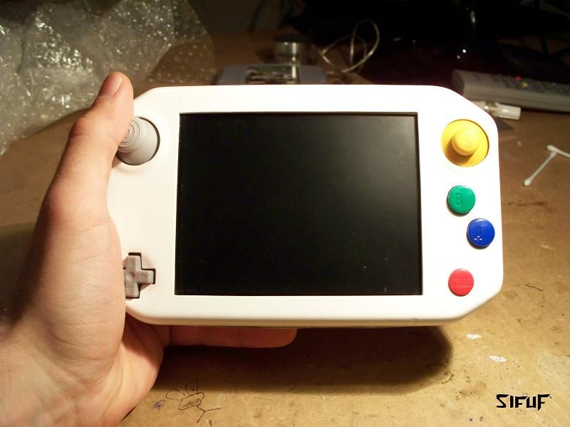
I am making a Wii portable and need to construct a circuit capable of converting analog stick signals into D-Pad signals when a trigger button is depressed. The reason: I want to use a giant 3W speaker and a 5.6" LCD and don't have any room on the front of the portable for a D-pad.

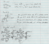
The idea is that since a GameCube controller is set up to where you almost never have to press the d-pad while moving the analog stick, one could potentially use the analog stick as the D-pad. I just need to figure out how to make the joystick-to-D-pad circuit only turn on when I press a trigger button. (Which will look like a Z-button except on the right.) Any ideas on a circuit?
 
Joined
Mar 2, 2016
Messages
147
Likes
92


Many in the past on n64 portables opted to use c sticks for their c buttons based on preferences by mounting tact switches under each direction of the cstick.

Here's a crappy diagram of what im talking about:
Untitled.png


as for making a toggle feature rather than a switch, you could try to find a toggleable switch to make your life easier, you'll have to make a circuit that will switch the grounds of the analog stick and dpad otherwise.

You should try to make room for a dpad, but this is the easiest option.
 

YveltalGriffin

First Wii U Trimmer
.
Joined
Jun 7, 2016
Messages
303
Likes
1,106
Location
South Florida
Portables
5
Thanks for the help. I'm most interested in the solution involving comparators. (I like making circuits.) However, the extent of my knowledge of circuits is measly, and transistors especially are tough for me to understand. Could you elaborate on the conparator thing?
 

cheese

the tallest memer in town
Staff member
.
.
.
Joined
Mar 2, 2016
Messages
2,759
Likes
2,431
Location
Florida
An op amp would be the easiest comparator to use, as you input two voltages, power and ground, and it will output either positive voltage or ground depending on which voltage is greater. Here's a sample of what I mean (sorry my handwriting is bad...):
out.png
 

Aurelio

ᕕ( ᐛ )ᕗ
Staff member
.
.
.
.
.
Joined
Mar 3, 2016
Messages
2,228
Likes
2,952
Portables
2
An op amp would be the easiest comparator to use, as you input two voltages, power and ground, and it will output either positive voltage or ground depending on which voltage is greater. Here's a sample of what I mean (sorry my handwriting is bad...):
View attachment 739
Yes, exactly what I meant.
A couple additional things:
- Make sure to get an op amp that can be powered with a single supply (+V and GND). Since you need 4 op amps you can use an LM239.
- To add the possibility to enable the circuit by pressing a button, use a button as an output enable for 3-state buffers (such as 74HC125). You want to place each one of the buffers between the output of each op amp (connected to the input of the buffer) and the npn transitor (the base connected to the output of the buffer). Also you should add a pull-down resistor to each base of the transistors to make sure that they are always disabled when the button is not pressed.
 
Top