Question 6-Layer trim shows some signs of life and then remains black screened

Joined
Feb 21, 2020
Messages
24
Likes
11
Okay! So I recently got some RVL-PSUs sent to me by way of PCBWay and I wanted to get back into the trimming game with yet another wii!

The Basics:
- 6 Layer Board
- Modded with RVLoader
- U10 Relocated and validated pre-trim.
- I don't really care about wii features, I'm basically just trying to make a small melee machine.


I trimmed my wii tonight and I didn't think it was any different from the other wii boards I've trimmed. This is technically the farthest I've gotten with a 6 layer board and I still can't seem to get it to boot to RVloader post trim.

What's happening?
- After wiring up everything and powering the various components, I see the TV flash a horrifying bunch of pixels and then simply black screen.
- After checking the voltages of each component that needs power, I can verify I'm getting approximately 1v, 1.5v, 3.3v, and I've bridged the onboard Sharp regulator to receive 1.8 in the two places it needs.
- And yes, I sanded with 200, 400, 600, and 800 grit on the sides

Some things I'm considering
- I verified the U10 working and I taped it in place to verify it worked pre-trim. I also re-inserted it just as a double-check measure post-trim after an attempt at powering it.
- Is it possible that I'm leaving too much extra board? will any of the components on the periphery of the trim line interfere with my ability to see the damn Rvloader boot text?
- I did a modified trim (not exactly OM6 but closer to what Jeff did with his wii micro stuff) and I"m wondering if it's way more risky with 6-layers. I remember reading that they're more unknown than four layers. is trimming it while retaining the USB / A/V just... a difficult thing?

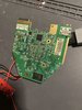
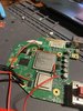
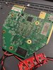
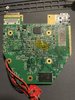
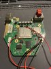
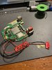
Attached a video of my whole situation and pictures of my RVL-PSU and 6-Layer.

For additional context, I'm adding a zip file containing a video of my problem and also showing me booting it! I have to zip it because the forums don't allow me to raw post vid RIP.
 

Attachments

CrazyGadget

Crazy Helpful, CrazyGadget
.
Joined
Jun 6, 2020
Messages
607
Likes
870
Location
Downing's Closet
Portables
???
3 things:
-Did you check the resistances between your voltage lines after you sanded, as per Nold's forum guide?
-Is the U10 wire even soldered to the via? It looks to just be "inserted," not soldered. That could be an intermittent connection, causing your issue.
-I'd reflow a bunch of those joints on the Wii / PSU with some flux and an iron to get some smoother joints.

As a side note, it's good that you have a couple grounds going between the Wii / PSU. While I don't think it matters much (but technically could cause ground loops), I like to take from one ground pad on the PSU and solder it somewhere on top of the wii, and then take another ground pad on the PSU and solder it somewhere on thr bottom of the Wii. Again, ground loops? Technically. Has it ever caused issues in my experience? No.
 

Stitches

2 and a Half Dollarydoos
Staff member
.
.
Joined
Feb 5, 2017
Messages
3,815
Likes
3,008
Location
Banana Bender Land, Australia
Portables
6
Now that's a close shave
1679050665555.png


What power supply are you using for this btw? 6 layers use a lot of juice, is it able to supply 15w to the system?
 
Joined
Feb 21, 2020
Messages
24
Likes
11
3 things:
-Did you check the resistances between your voltage lines after you sanded, as per Nold's forum guide?
-Is the U10 wire even soldered to the via? It looks to just be "inserted," not soldered. That could be an intermittent connection, causing your issue.
-I'd reflow a bunch of those joints on the Wii / PSU with some flux and an iron to get some smoother joints.

As a side note, it's good that you have a couple grounds going between the Wii / PSU. While I don't think it matters much (but technically could cause ground loops), I like to take from one ground pad on the PSU

and solder it somewhere on top of the wii, and then take another ground pad on the PSU and solder it somewhere on thr bottom of the Wii. Again, ground loops? Technically. Has it ever caused issues in my experience? No.
I had genuinely not considered that simply inserting would cause connectivity issues because yeah, that makes sense. I should totally solder that wire to the via so it's connected.

I have a multimeter and I'll need to actually look up how to test resistances but this is something else I haven't done. I'll make sure I test it.

And to your 3rd point: yeah my soldering acumen is still very very weak so I'll get a better tip to disperse heat onto some of these bigger joints (I'm using basically a pencil tip which might just be not enough surface area to get a good flow on to the joints)

For the ground pad on the PSU stuff, is it sufficient for me to only ground two of the pads from the RVL-PSU onto the wii? I was under the impression I'd need to ground every pad that has a voltage (except for 5v since I didn't bridge it)


Now that's a close shave
View attachment 26615

What power supply are you using for this btw? 6 layers use a lot of juice, is it able to supply 15w to the system?
I'm using a Laptop power supply that's capable of outputting that, yeah. (It's this one) but would my USB-C breakout board be a limiting factor there? (These are what I'm using) I'll need to look into this too I think.

Edit: After looking into that listing and seeing a single review that MENTIONED its usage in a raspberry pi I'm wondering if this is the limiter:

From the review
What I found worked were these break-out boards and the 100-watt USB cable with the meter. The photo attached is using the USB C adapter for the Raspberry Pi 4.

What makes these different is the two resistors. The resistors tell the USB C charger to supply 5 volts at 2 amps or 10 watts. This board along with a good quality USB C cable solved my low-voltage issues.

Thanks for the leads on solving this problem y'all. I'll report back!
 
Last edited:
Joined
Feb 21, 2020
Messages
24
Likes
11
Update on resistances:

I uh. It was very hard to wait for the resistance to kind of stabilize, but I noticed when trying to measure them, sometimes my multimeter wouldn't react at all (even controlling for what level I was at, 200 for most and then jumping to 20k for the 3.3v checks). I'm assuming this is because the soldering is messy or bad?

I re-did some soldering on the 3.3v and was able to get readings so I'm assuming I just botched that bit of it in some ways, because it seems like with some of the blobs, I have to really find a "sweetspot" for my multimeter needles to prod to start getting readings which should indicate that my flowing of these joints includes a lot of bad continuity, right? or something else. because these resistance readings feel WAY off base. Anyways here's what I got:


COM1v1.15v1.8v3.3v
GND~12~36~29~15.5k
1v~48~42~16.8k
1.15v~82~14.5k
1.8v~14.3k

As you can see... a lot of these numbers (especially for 3.3?) seem... super high? I actually have no idea what high resistance means? I'm hoping it's just "lol you soldered bad, bud. redo it"
 

CrazyGadget

Crazy Helpful, CrazyGadget
.
Joined
Jun 6, 2020
Messages
607
Likes
870
Location
Downing's Closet
Portables
???
All those resistances seem okay to me. The fact there are no dead shorts is a good sign. The voltage lines' loads are not purely resistive; they have a capacitive load as well - this causes the "jumping" you see on the 3v3 line. That's actually a good sign!!! Every meter seems to act a little differently on where it stabilizes, I've had some meters cap around 8k, some 16k like you see, and some depend on the range you have it set at, etc...

Regarding the PSU / grounds, for a 6-layer wii, you *need* at least 2 grounds between the wii and the psu. All grounds on the wii are interconnected on the board, all grounds on the psu are interconnected on the board. It's a matter of connecting the two boards' grounds, so any ground point on the PSU can connect to any ground point on the wii. Just need 2 grounds between the 2 boards.

I can't speak for the supply you're using, but it'll be worth it for you to pick up a 12V 2A wall wart from Amazon, as you will end up using it for the noldendo anyway. That way you can rule your supply out of the equation.
 
Joined
Feb 21, 2020
Messages
24
Likes
11
Funnily enough I've had the RVL-PSU by-way-of-USB-c work on my four layer board. but maybe I just need to go with a DC jack noldendo style. I've plugged it in after checking everything and trying to reflow pads but now it won't even give me the gross mess of pixels (which is a damn shame because it's actually a beautiful trim I've done and I'm super proud of it!

All that said I'm gonna grabsome DC power jacks, a wall wart, and wait for some 90% isopropyl to come through so I can clean up the flux residue from cleaning.
Hoping it's not dead in the water! just gotta be patient.
 

CrazyGadget

Crazy Helpful, CrazyGadget
.
Joined
Jun 6, 2020
Messages
607
Likes
870
Location
Downing's Closet
Portables
???
If your USB C board is configured to negotiate 5V @ 2A (10W), it won't be enough to power a 6-layer (appx 12W). Have you checked your voltages when you try to power on? If the input voltage / PSU voltages are sagging really bad, it's likely hitting the current limit.
 
Joined
Feb 21, 2020
Messages
24
Likes
11
If your USB C board is configured to negotiate 5V @ 2A (10W), it won't be enough to power a 6-layer (appx 12W). Have you checked your voltages when you try to power on? If the input voltage / PSU voltages are sagging really bad, it's likely hitting the current limit.
This actually greatly interests me. I did notice that with this board some of my voltages would sink below their guaranteed limit. I imagine it's the board in this case then. I suppose it would make sense that I was able to power a 4 layer with the current board / setup I have because it generally draws less, correct?

This is all super helpful information, so thank you for this!

Edit:

Actually I realize I have a 20v breakout board that negotiates 20v (USBC) and a couple of buck converters. I think I might try to frankenstein a more compatible negotiation for my PSU and see if that works over the weekend
 

CrazyGadget

Crazy Helpful, CrazyGadget
.
Joined
Jun 6, 2020
Messages
607
Likes
870
Location
Downing's Closet
Portables
???
Max Vin of the PSU regs is 17V iirc, don't feed 20V straight in. Regarding the 4-layer, they only pull about 6W give or take, so if you only had 10W max, you'd be okay for that.
 

Stitches

2 and a Half Dollarydoos
Staff member
.
.
Joined
Feb 5, 2017
Messages
3,815
Likes
3,008
Location
Banana Bender Land, Australia
Portables
6
This actually greatly interests me. I did notice that with this board some of my voltages would sink below their guaranteed limit. I imagine it's the board in this case then. I suppose it would make sense that I was able to power a 4 layer with the current board / setup I have because it generally draws less, correct?

This is all super helpful information, so thank you for this!

Edit:

Actually I realize I have a 20v breakout board that negotiates 20v (USBC) and a couple of buck converters. I think I might try to frankenstein a more compatible negotiation for my PSU and see if that works over the weekend
Just make sure you don't feed 20v to the PSU or it gon fukken die
 
Joined
Feb 21, 2020
Messages
24
Likes
11
Update:

I've replaced my usbc with a wall wart 12v dc input, I'm feeding power everywhere it needs to go, I've tested the U10 via in both places, I get a static screen when booting, the AUX prompt on my TV goes away, and I just stare at black screen while the CPU/GPU heat up.

I'm running two ground wires: one from the RVL-PSU to the topside ground of the board, and one from the PSU to the underside ground of the board. I actually think as far as trims go this one was my best one, and I can't easily find any faults.

I verified continuity, power, etc, and I'm truly at a loss for how I can move forward so I might just relegate this to the shit pile of other 6-layers I've already wrecked.

RIP.
 
Joined
Feb 21, 2020
Messages
24
Likes
11
update update: I trimmed an entirely new 6-layer, taking forward all the learned lessons and it's booting! Only issue now is that when I supply power to 5v for USB it uhhh.. doesn't know usb is there.

I guess this is a problem for future mork.
 

Stitches

2 and a Half Dollarydoos
Staff member
.
.
Joined
Feb 5, 2017
Messages
3,815
Likes
3,008
Location
Banana Bender Land, Australia
Portables
6
update update: I trimmed an entirely new 6-layer, taking forward all the learned lessons and it's booting! Only issue now is that when I supply power to 5v for USB it uhhh.. doesn't know usb is there.

I guess this is a problem for future mork.
Give us some pics when future Mork gets around to it. We gotta get this project moving along!
 
Joined
Feb 21, 2020
Messages
24
Likes
11
Give us some pics when future Mork gets around to it. We gotta get this project moving along!
Okay, I ended the night LATE, but I believe I understood the problem.

Essentially, in the future if I'm using a heat gun to remove the memory card port pins, I should cover the components that run downstream of the USB with thermal tape so they don't... move.

basically I tried heatgunning the pins of the memory card and at some point the solder came loose from the DA7 component (which looks like is the component that hits just after CM1 for the USB trace).
Image

Basically I THOUGHT I may have screwed myself here. In the pictures you see a DA7 component because I TRIED to grab one from another dead board and replaceit to see if that just... "worked" lol.

Spoiler: it did not.

But I also managed to test-wire up a USB breakout board to the traces (much like I did with my original 4-layer trim) and it was reading! So I think I may have just borked the usb ports on the board, which is unfortunate, but I have a way forward by way of direct-to-trace wiring.

Image
 
Last edited by a moderator:

CrazyGadget

Crazy Helpful, CrazyGadget
.
Joined
Jun 6, 2020
Messages
607
Likes
870
Location
Downing's Closet
Portables
???
You could just run a twisted pair from the vias to the pins on the port. You won't have the protection from CM1/2, but you'll restore the onboard USB ports' functionality.

Regarding the memory card ports, I find it much easier to physically break thr plastic / metal retaining brackets with some big wire cutters (it's not good for them, so use a pair you don't like). Once I've mangled the port and gotten it off, I desolder each of the pins one by one. Better than using a rework station and having the board sink that much heat.
 
Joined
Feb 21, 2020
Messages
24
Likes
11
You could just run a twisted pair from the vias to the pins on the port. You won't have the protection from CM1/2, but you'll restore the onboard USB ports' functionality.

Regarding the memory card ports, I find it much easier to physically break thr plastic / metal retaining brackets with some big wire cutters (it's not good for them, so use a pair you don't like). Once I've mangled the port and gotten it off, I desolder each of the pins one by one. Better than using a rework station and having the board sink that much heat.

Oh this is massive advice. I read this and then immediately yeeted my breakout board into the sun. Got the wires twisted to 2 and 3 and holy shit I really do just need a second color magnet wire, red by itself is just hard lol. Hot glued the wires into place because I was afraid of things moving and not working, but I expect in the future to not need it.

So to recap:

Using onboard now, only one port works (totally fine I don't give a FUCK about the other USB port, all my homies hate the second USB port) but it's booting!

I actually have a question while I'm here. When I look at the Noldendo thread, I see this rewiring:

1679334303038.png


The usb 5v to the C110... whatt is that doing? is theC110 component actually providing 5 volts here? I'm just trying to make sense of that bit.
I can only assume... yes?
I need to read more lmao.
 

Benge

.
Joined
May 18, 2020
Messages
202
Likes
691
Location
France
Portables
4 : O-Wii (V1,V2,V2.1)/ BS2
Oh this is massive advice. I read this and then immediately yeeted my breakout board into the sun. Got the wires twisted to 2 and 3 and holy shit I really do just need a second color magnet wire, red by itself is just hard lol. Hot glued the wires into place because I was afraid of things moving and not working, but I expect in the future to not need it.

So to recap:

Using onboard now, only one port works (totally fine I don't give a FUCK about the other USB port, all my homies hate the second USB port) but it's booting!

I actually have a question while I'm here. When I look at the Noldendo thread, I see this rewiring:

View attachment 26670

The usb 5v to the C110... whatt is that doing? is theC110 component actually providing 5 volts here? I'm just trying to make sense of that bit.
I can only assume... yes?
I need to read more lmao.
Yea the red wire is connected from that capa to send the 5V to the USB since the trim process cut the internal 5V copper track
 
Top