loopj
.
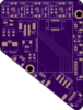
Hey all, I've just open sourced my Wii motherboard breakout PCB in case anyone finds it helpful for their projects.
I've found it to be useful for prototyping, or for permanent installation on Wii projects which are mounted with the CPU/GPU facing up (probably not most portables, since they are typically mounted CPU-down).
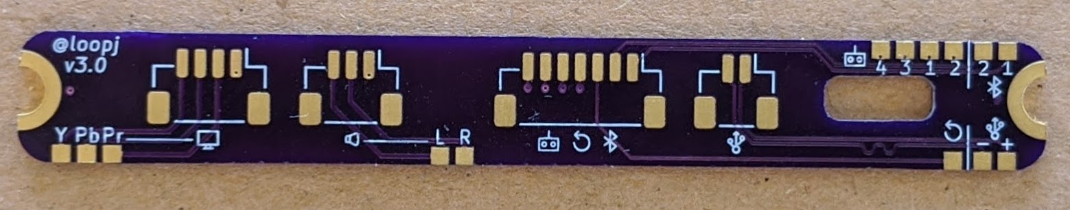
This is designed to be permanently mounted to a (trimmed) Wii motherboard to give access to peripheral data lines without having to worry about breaking small wires. I designed this allow me to rapidly prototype "daughterboard" peripheral PCBs without having to de-solder/re-solder.
Here's the project on GitHub.
Some features
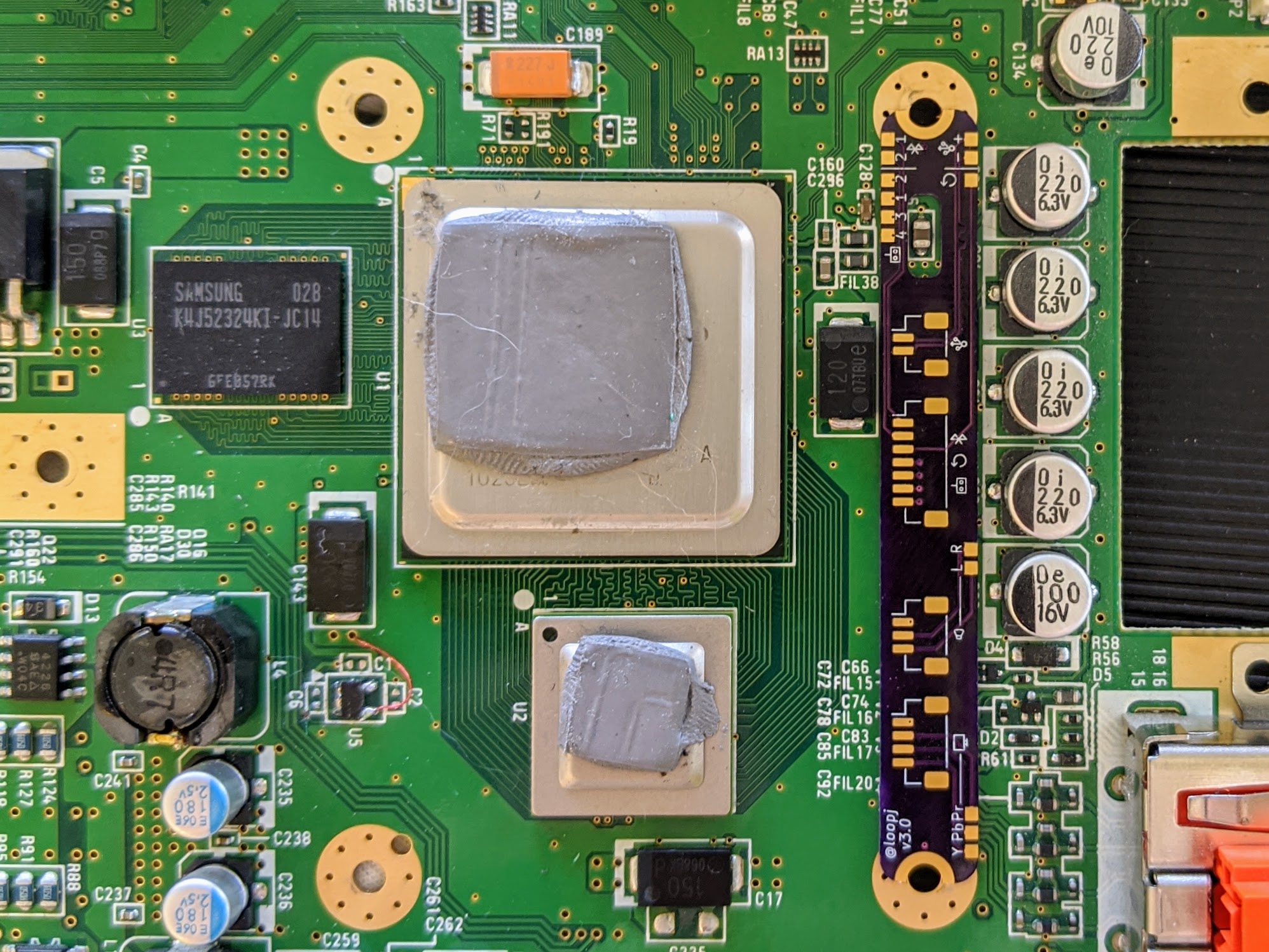
I've found it to be useful for prototyping, or for permanent installation on Wii projects which are mounted with the CPU/GPU facing up (probably not most portables, since they are typically mounted CPU-down).
This is designed to be permanently mounted to a (trimmed) Wii motherboard to give access to peripheral data lines without having to worry about breaking small wires. I designed this allow me to rapidly prototype "daughterboard" peripheral PCBs without having to de-solder/re-solder.
Here's the project on GitHub.
Some features
- Pads aim to be as close to onboard vias as possible
- Designed to lay flush with 4-layer Wii motherboards
- Cutout for capacitor (C56)
- Can be screw mounted (M2 or M2.5 screws), glued, or soldered
- Castellated mounting holes
- Footprints for vertical JST-SH headers
- Breaks out:
- USB (D-, D+)
- Audio (L, R, GND)
- Component/RGB Video (Y, Pb, Pr, GND)
- Bluetooth (D1, D2)
- GameCube Controllers x4 (SI lines)
- Reset Line