
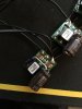
If there's no USB detected, there is a blank screen for 10-20 seconds before Postloader's error screen appears. How long did you leave the black screen up for before turning the Wii off?Okay, been a while since I last was here but life kinda got busy. I've been back working on my portable for about a week now. I got the board cut and power regulators wired up so I could test the board. Got nothing onscreen unfortunately so I'm guessing I got a short somewhere, here are some pictures too.
View attachment 6233 View attachment 6234 View attachment 6235 View attachment 6236 View attachment 6237
Worklog Unnamed Wii Portable 2nd attempt
- Thread starter Green_Saint
- Start date
- Joined
- Sep 17, 2016
- Messages
- 25
- Likes
- 0
Well I'm not 100% sure but I might of left it for about 10-15 seconds. I'll give it another go either in a second or tomorrow since right now I'm just cleaning up some areas that looked iffy. I took the USB off of the chunk of board I had it on too just in case there was something happening there
- Joined
- Sep 17, 2016
- Messages
- 25
- Likes
- 0
Okay I just tested it now and after a long amount of time I still had a blank screen 
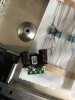
Here's a picture of my regs, I'm assuming negative connects to the middle pin while positive is connected to the input pin right?
Here's a picture of my regs, I'm assuming negative connects to the middle pin while positive is connected to the input pin right?
Last edited:
Correct, but that photo makes it kinda looks like you've soldered the outputs together as well. You didn't do that, right?Okay I just tested it now and after a long amount of time I still had a blank screen
Here's a picture of my regs, I'm assuming negative connects to the middle pin while positive is connected to the input pin right?
View attachment 6239
Also, you should check the Wii for shorts with a multimeter. And check the output of the regs to be sure they're putting out the correct voltage.
- Joined
- Sep 17, 2016
- Messages
- 25
- Likes
- 0
Wait I did do that... why did I do that XD I must of just been on autopilot soldering the wires on ahahaha. Well I’ll get those soldered off but with checking my regs, when I try to with my multimeter I end up with a different number every time or they will all have the same number of resistance so I figured my multimeter was being weird. I saw that soldiering the positive and negative the wrong way round that you can kill the regulator but I’m pretty sure I haven’t done that.
If you had the outputs connected, you've probably killed the Wii. The regs might be okay, but I'm pretty sure that dumping 5v into the 1v line kills the Wii.Wait I did do that... why did I do that XD I must of just been on autopilot soldering the wires on ahahaha. Well I’ll get those soldered off but with checking my regs, when I try to with my multimeter I end up with a different number every time or they will all have the same number of resistance so I figured my multimeter was being weird. I saw that soldiering the positive and negative the wrong way round that you can kill the regulator but I’m pretty sure I haven’t done that.
- Joined
- Sep 17, 2016
- Messages
- 25
- Likes
- 0
Owch... well that sucks, I kinda can’t get a hold of another Wii right now so I guess this is going back on hold for me : /
- Joined
- Sep 17, 2016
- Messages
- 25
- Likes
- 0
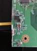
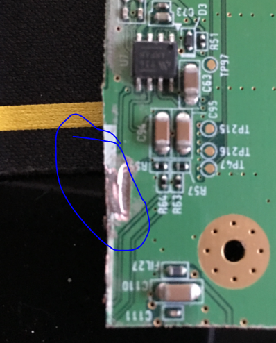
Well I got a new board but while cutting it this happened, should I assume the board is dead?
Attachments
-
 1.8 MB Views: 245
- Joined
- Dec 10, 2016
- Messages
- 578
- Likes
- 663
- Location
- Constant Fear
- Portables
- sin^2(x) + cos^2(x) +e^(i*pi)
:Swoosh:
I think it's fine, just sand it so it doesn't short...
assuming we are talking about this
I think it's fine, just sand it so it doesn't short...
assuming we are talking about this
- Joined
- Sep 17, 2016
- Messages
- 25
- Likes
- 0
Oh, I figured since I went through some layers I thought it was dead. I'll sand it soon
- Joined
- Sep 17, 2016
- Messages
- 25
- Likes
- 0
I just want to make sure that I solder everything correctly on the custom regs this time so to be crystal clear. I connect positive in into the input, negative goes into the middle pin (ground I think?) then output connects to where they need to be, and finally I can connect all the regs together on the input and middle/ground pin yeah?
Correct. The inputs are all connected together with your input (power switch), gnd are all connected together, and then connected to gnd on the board, and output goes to each appropriate spot on the board. What you have now looks good but it looks like you are missing the resistor though. Also be aware (can't tell from the pic) the capacitor can only be connected one way. The leg with the gray stripe should be gnd.I just want to make sure that I solder everything correctly on the custom regs this time so to be crystal clear. I connect positive in into the input, negative goes into the middle pin (ground I think?) then output connects to where they need to be, and finally I can connect all the regs together on the input and middle/ground pin yeah?
View attachment 6560
- Joined
- Sep 17, 2016
- Messages
- 25
- Likes
- 0
No I do have the resistors soldered on, you can see it at the back behind that bit with the label on, and yeah I have both negative's on the inner side since I saw an image with them like that