Introduction
This guide and its graphics were created by me, to the best of my knowledge and certain. But without guarantee of correctness! (Even if everything has been tested by me)! So make sure that you know what you are doing, as I will not be responsible for any damage or harm you might do to your Dreamcast or yourself!
I used the BitBuilt-Logo in every graphic, but just as an advertisement and appreciation for this site and its community. But BitBuilt has nothing to do with this work
Special thanks to Aurelio for motivating me to trim further and pre-reading this guide & RDC for supplying scans of the DC Mainboard.
Also much thanks to the DC-Homebrew-Scene and the BitBuilt-Community!
If you have any questions/corrections/comments feel free to ask.
Prerequirements
GD-ROM Replacement
BIOS-Mod
Trimming
Reconnecting Traces
After trimming there will be two things to reconnect:
5V to IC401
RTC-Battery Voltage
Audio-DAC Relocation
Power and Voltage
No FAN Fix
AICA Audio-RAM-Clock
Controller
Serial-/SD-Card
RTC-Battery
Video Output And Forcing VGA-Mode
G1-ATA
Changelog
15.04.18: Updated Video-Output Pinout
16.04.18: Correction Video-Output Pinout(s)
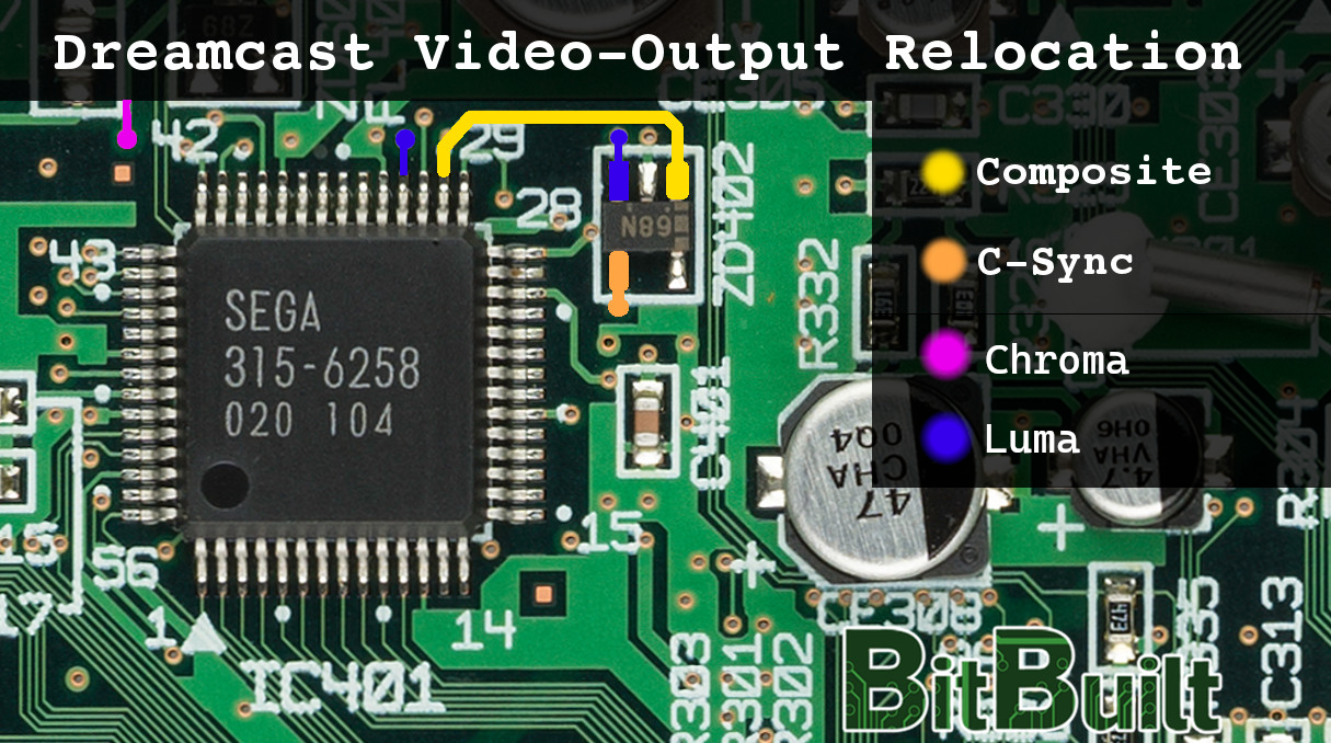
09.04.24: (Wesk) Added Chroma and Luma pinouts to AV diagram
This guide and its graphics were created by me, to the best of my knowledge and certain. But without guarantee of correctness! (Even if everything has been tested by me)! So make sure that you know what you are doing, as I will not be responsible for any damage or harm you might do to your Dreamcast or yourself!
I used the BitBuilt-Logo in every graphic, but just as an advertisement and appreciation for this site and its community. But BitBuilt has nothing to do with this work
Special thanks to Aurelio for motivating me to trim further and pre-reading this guide & RDC for supplying scans of the DC Mainboard.
Also much thanks to the DC-Homebrew-Scene and the BitBuilt-Community!
If you have any questions/corrections/comments feel free to ask.
Prerequirements
GD-ROM Replacement
Since we do not want to use the original GD-ROM in our DCp, we will have to replace it with something smaller/better. There are basically two possible solutions for this:
1. USB-/SD-GDROM
An FPGA-Based board, enabling you to play games from a USB-Drive/SD-Card
Pros:
- Play ROMs from USB-Drive / SD-Card
- No custom BIOS Required
- Very good ROM compatibility
Cons:
- Expensive
- Requires extra hardware
2. G1-ATA-Mod
A relatively “simple” mod, for which you wire a standard ATA/IDE Hard-Drive/CompactFlash-Card to the DC’s GD-ROM ATA-interface. But that requires a custom BIOS-Chip and good soldering skills
Pros:
- Cheap / No special hardware required
- Play ROMs from IDE-/SATA-Harddrive or CompactFlash
Cons:
- Many wires to solder
- Requires custom BIOS/-Chip (“Dreamshell no-gdrom”)
- Requires AICA-Clock workaround
- Worse ROM compatibility than GDROM-Replacement
In this guide I will just cover the G1-ATA method!
BIOS-Mod
So before trimming your DC, you should have a custom BIOS-EEPROM installed and flashed with the Dreamshell No-GDROM Bios. I will not cover it in this guide, since there are already enough resources on the web.
BIOS-Mod: http://www.mmmonkey.co.uk/sega-dreamcast-region-free-bios/
After this mod, flash the Dreamshell Bootloader BIOS called "boot_loader_retail_nogdrom.bios". It will boot Dreamshell from SD-Card or G1-ATA.
BIOS-Mod: http://www.mmmonkey.co.uk/sega-dreamcast-region-free-bios/
After this mod, flash the Dreamshell Bootloader BIOS called "boot_loader_retail_nogdrom.bios". It will boot Dreamshell from SD-Card or G1-ATA.
Trimming
Here is the trim I figured out. Of course it should be possible to cut even further. But that’s up to you ;-)
When doing this trim, you will have to relocate the Audio-DAC Chip (IC303) before trimming and solder to small pads. Also you will have to reconnect two traces. But you will find all the needed information to do so in this guide.
Make sure that you cut OUTSIDE of the red lines and then carefully sand all the edges with at least 800 grid.
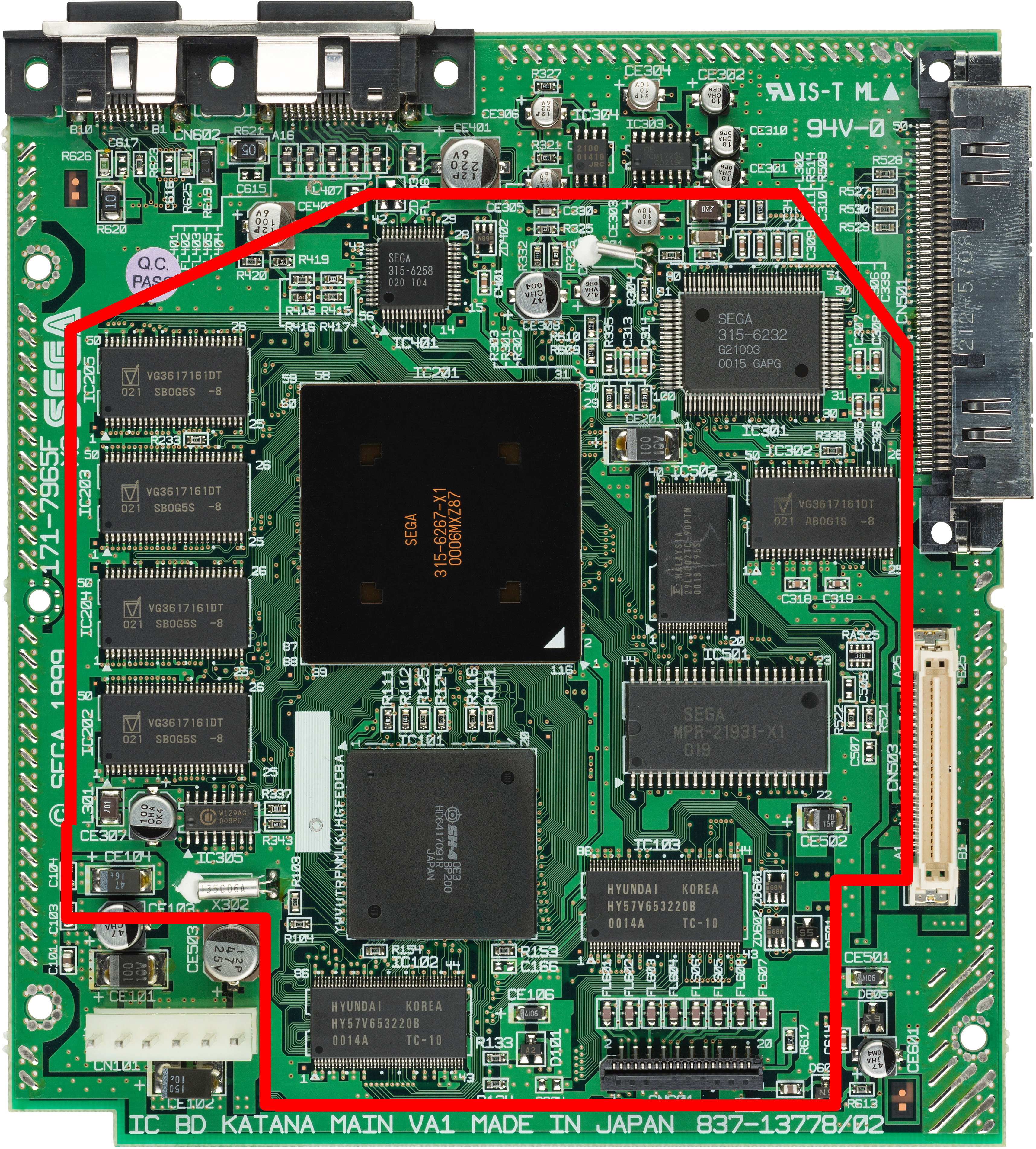
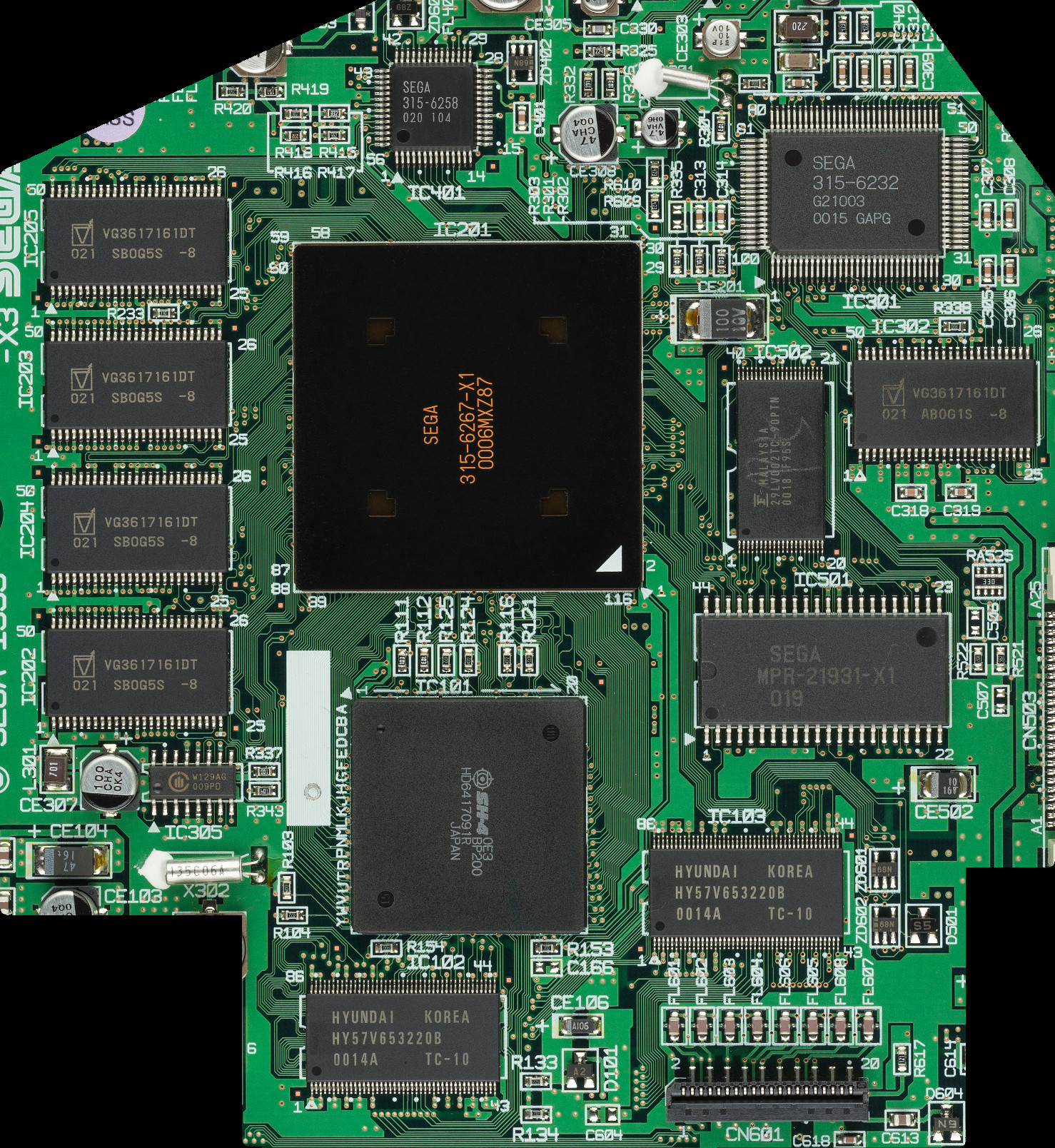
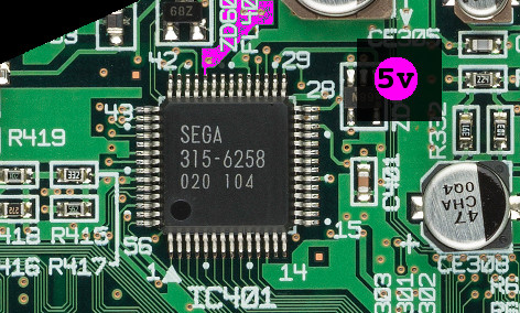
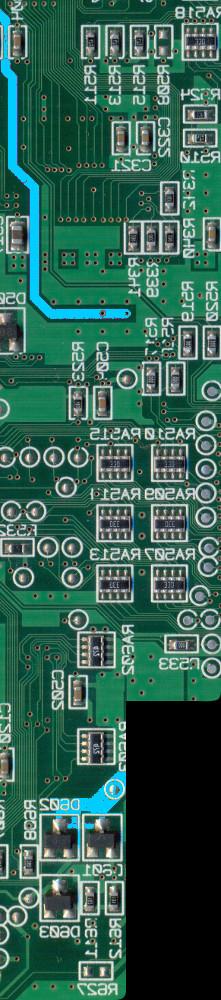
Reconnecting Traces
After trimming there will be two things to reconnect:
5V to IC401
Reconnect the shown trace to 5V.
RTC-Battery Voltage
Reconnect the shown traces.
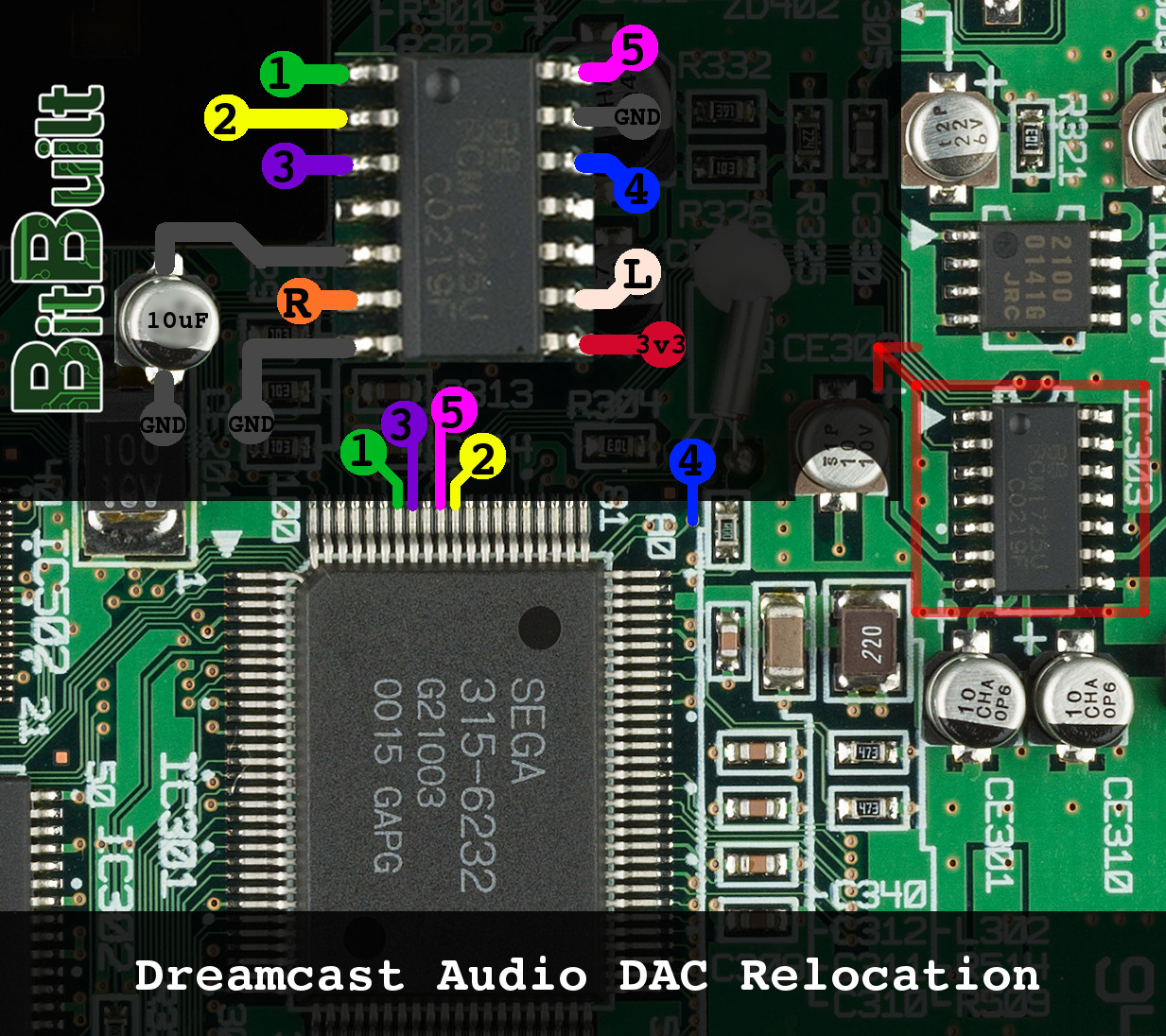
Audio-DAC Relocation
Unsolder IC303 BEFORE trimming and reconnect it as shown. You can also reuse the 10uF capacitor CE301 or CE310 for pin 5 of the DAC-IC.
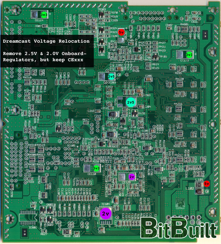
Power and Voltage
Main Voltage lines:
12v (Used by GD-ROM, not needed to boot and not covered in this guide)
5v (0.42A)
3.3v (2.8A when powering onboard-regulators, 0.4A without the)
Onboard Regulators:
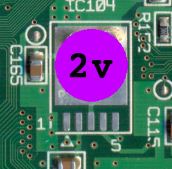
2.5v (1.6a)
2.0v (0.75a)
All regulators should be replaced with custom regulators to reduce total power-consumption drastically to <= 10W.

12v (Used by GD-ROM, not needed to boot and not covered in this guide)
5v (0.42A)
3.3v (2.8A when powering onboard-regulators, 0.4A without the)
Onboard Regulators:
2.5v (1.6a)
2.0v (0.75a)
All regulators should be replaced with custom regulators to reduce total power-consumption drastically to <= 10W.
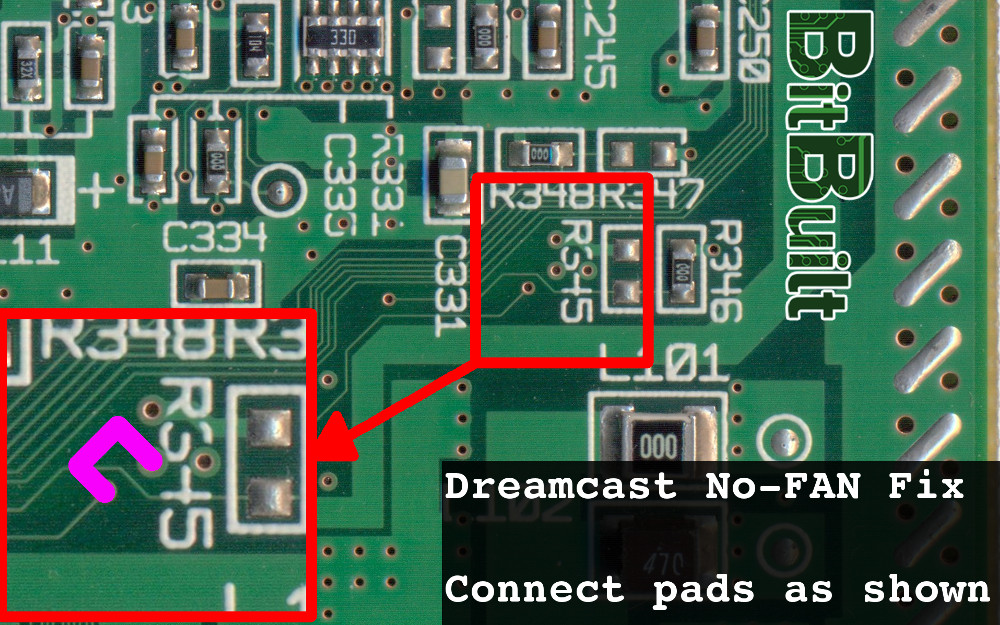
No FAN Fix
Normally the Dreamcast would not boot if there’s no PWM signal coming from a fan. The following workaround removes the need of a fan capable of outputting the correct PWM-Signal.
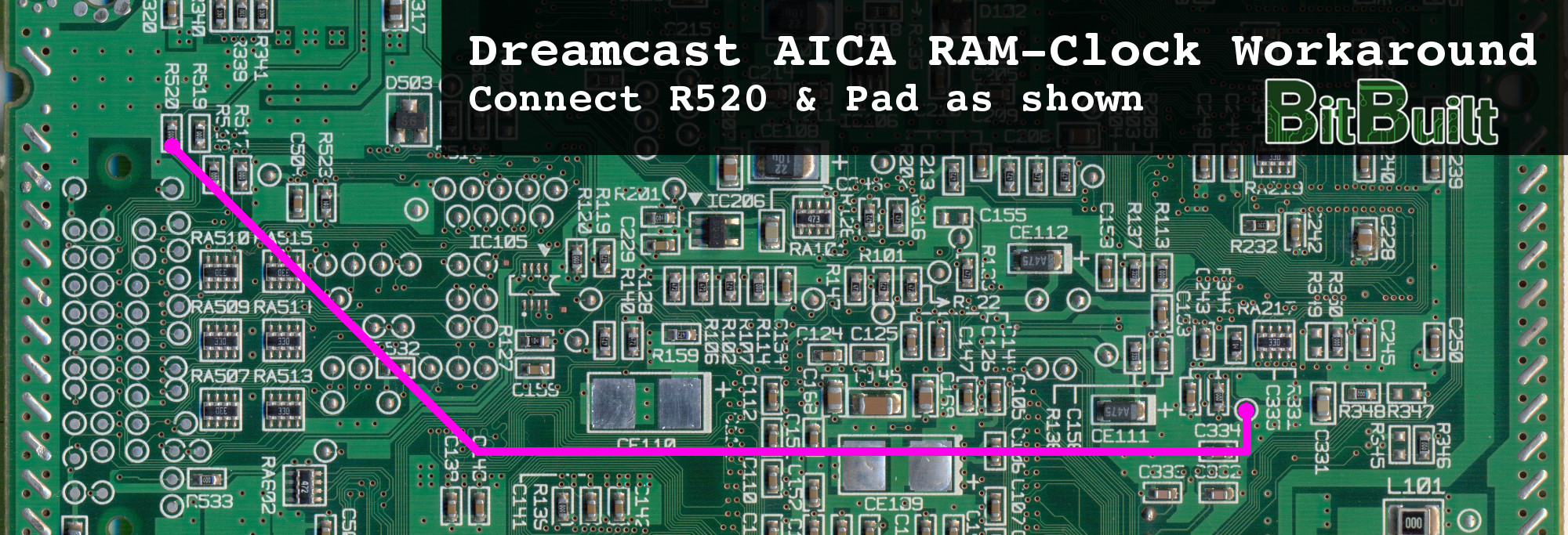
AICA Audio-RAM-Clock
Normally the AICA (DCs audio IC) will get it’s RAM-Clock from the GD-ROM. If you are not using a GD-ROM-Replacement like USB-GDROM, you’ll want to attach the internal 33MHz PLL Clock to the AICA as shown. Otherwise the DC will be super slow and it will not work.
Controller
Even after trimming you should still be able to use these pins:
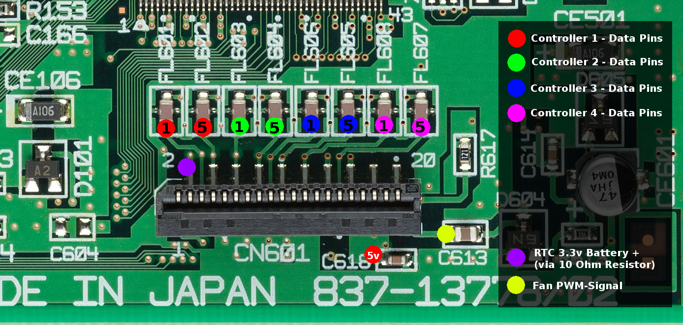
But you can also use these:
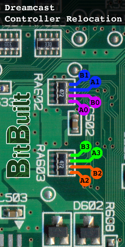
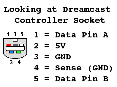
But you can also use these:
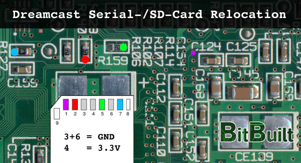
Serial-/SD-Card
Attaching an SD-Card to the DC is pretty much optional when using a GD-ROM replacement as it is much slower then the ATA-interface. But here is how to do it anyways:
RTC-Battery
The DC uses a rechargeable battery for its Real-Time-Clock which can be relocated as shown.
BUT DO NOT WIRE A NON-RECHARGEABLE BATTERY LIKE THIS!
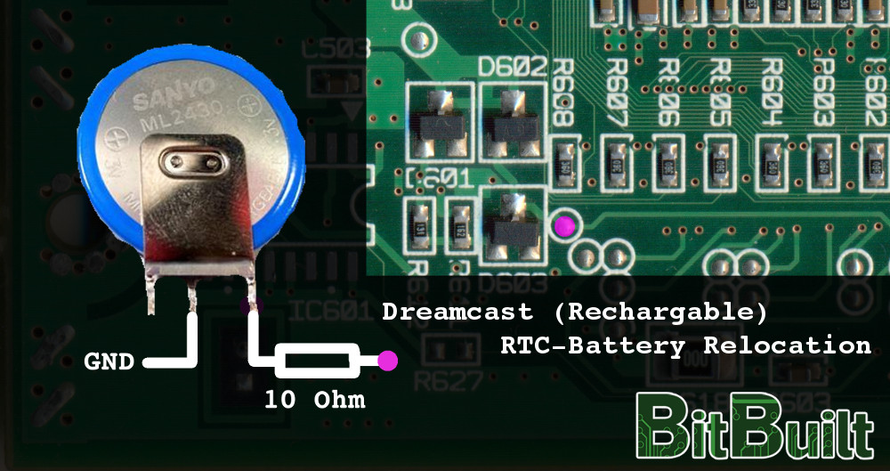
BUT DO NOT WIRE A NON-RECHARGEABLE BATTERY LIKE THIS!
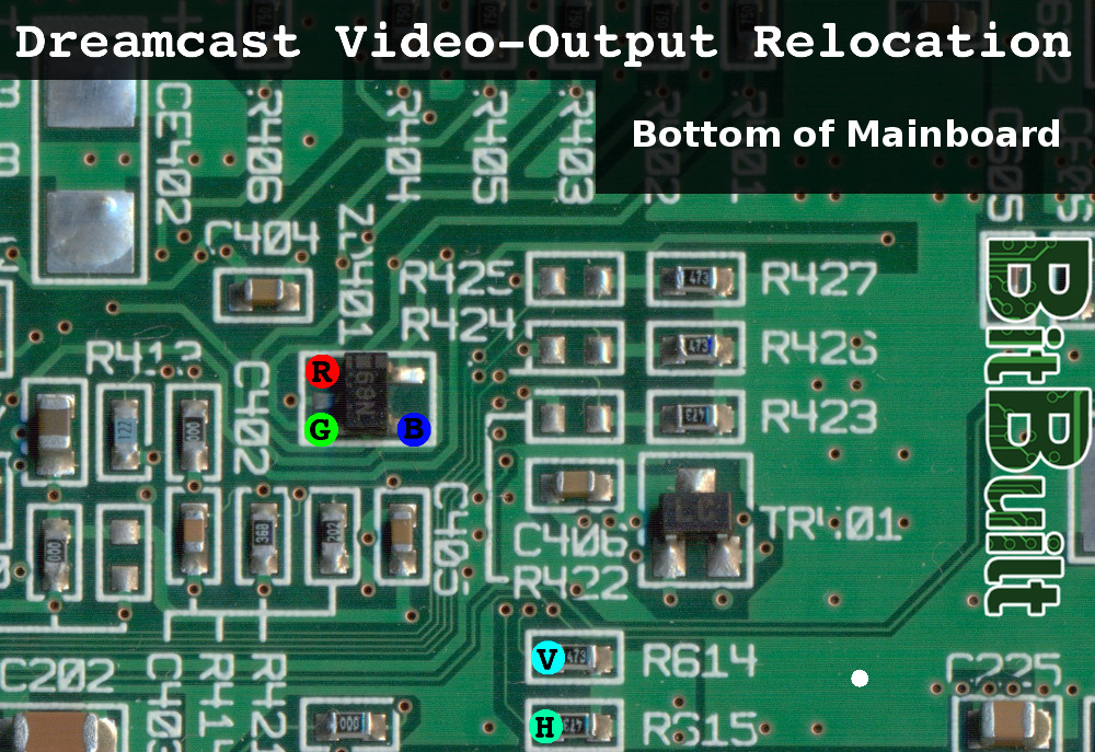
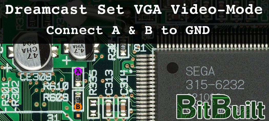
Video Output And Forcing VGA-Mode
The DC supports multiple video output formats. As you will most likely want to use VGA (best quality) here is how to enable VGA-Mode and wire it up.
Note: You will still need some external components to make VGA work, but you can ignore the VGA-Switch, because we wouldn't need to switch off VGA-output anyways.
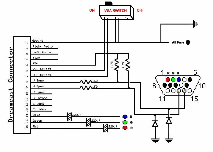
Source: http://www.mmmonkey.co.uk/dreamcast-internal-vga-mod/
Note: You will still need some external components to make VGA work, but you can ignore the VGA-Switch, because we wouldn't need to switch off VGA-output anyways.
Source: http://www.mmmonkey.co.uk/dreamcast-internal-vga-mod/
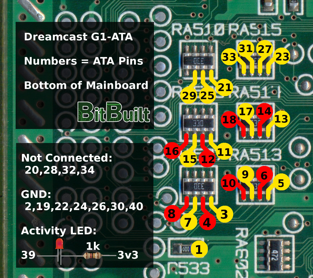
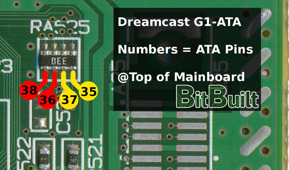
G1-ATA
G1-ATA is a “simple” mod, where you connect a standard IDE-Hard-Drive or CompactFlash-Card to the Dreamcast’s GD-ROM Port. This is an advanced pinout, that you can use after trimming.
Note: CompactFlash to SD-Card Adapters will work, too. But only with a horrible performance.
More info: https://fnhack.wordpress.com/
Note: CompactFlash to SD-Card Adapters will work, too. But only with a horrible performance.
More info: https://fnhack.wordpress.com/
Changelog
15.04.18: Updated Video-Output Pinout
16.04.18: Correction Video-Output Pinout(s)
09.04.24: (Wesk) Added Chroma and Luma pinouts to AV diagram
Last edited by a moderator: