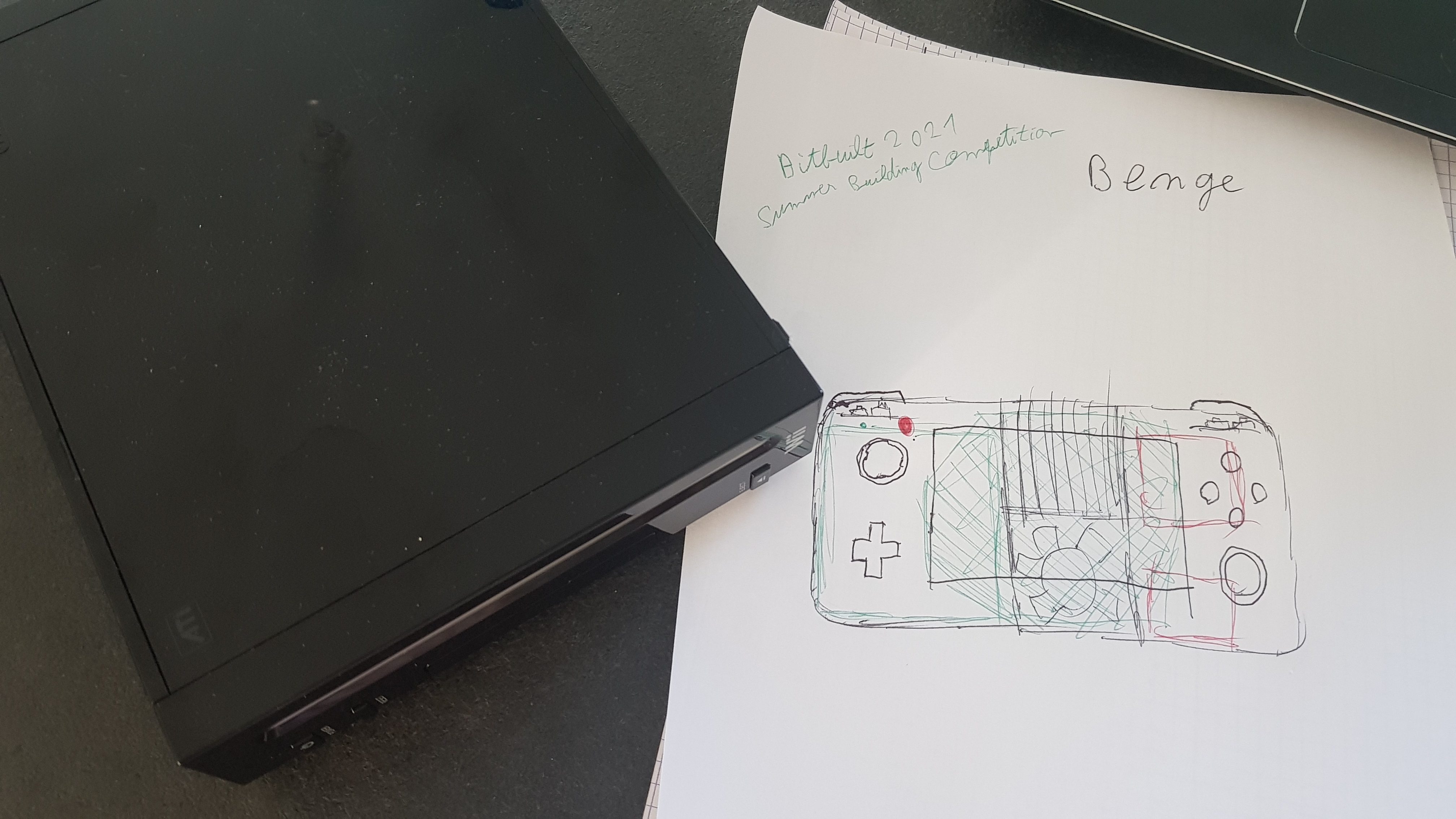
Today, I'm going to explain you what I want to do for the power board and USB data transfert.
The features I want :
- 1V/1.15V/1.8V/3.3V/5V regulators
- µSD to USB conversion on the board
- USB-C Power Delivery
- USB-C data transfers
- batteries temperature sensor
The goal will be to get all of this in a very small space !
The PMS will be based on Gman's RVL-PMS, it works well and also allows communication with the STUSB4500 for power delivery in USB-C.
For me, it's a very great solution because I don't want to code all from scratch, and I don't understand much about PIC.
I just know Arduino, and ESP32, and I learned the basics of C, C ++ in class ... but I suck at programming.
To save as much space as possible on the pcb I will first use regulator "all in one" :
TPS8208x
Now to transform the signal from a µSD card to USB I will use this circuit :
GL823K, it has an integrated quartz so no need to add an external one.
And finally, for the USB power delivery and data transfer part, the
Gman website was a great help in understanding how all of this works.
But the concern is that I don't want to add an additional 5V regulator, a 3.3V LDO and a power multiplexer.
I saw that on the new version of the PMS PD, there was not all that.
So I think the 5V regulator is controlled independently of the others regulators, and turns on when a voltage is detected on the USB-C.
And you no longer need to use a 3.3V LDO if you power the USB multiplexer from the batteries and use its ultra low consumption function when not in use.
For the moment I have almost finished completing the diagram, but I'm stuck on one thing :
how to activate 5V regulator with two activation sources ?
I thought to take the voltage which activates Q1 to activate a transistor which would make pass a tension in D1.
But the voltage varies according to the input voltage (5V/9V/12V ...) so it won't work.
And I'm not sure whether to use two diodes to have two sources of activation is a great idea :/


")


