- Joined
- Aug 2, 2016
- Messages
- 294
- Likes
- 144
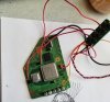
If you trim neatly around the ports and give the edges a good sand, you can totally use the original ports while they're attached to the PCB. I think the person who told you that may have meant that you can't use ports that are still connected to the mobo proper. You can cut the board closely around the ports and they'll work just fine.performed the trim and made sure to use 1500 grit sanding paper along the edges of the board, but following gmans image for reference keeping the 4th screw post. if i remember correctly someone said that the console ports (av out/power) won't work if the board is still attached. can someone answer that because i don't have any other usb ports at the moment and i can't desolder anything until i get a desoldering iron. after i get confirmation ill be testing the power regulators as well, ill probably end up saving the power mii lite board i got which looks awesome.View attachment 9190
ok cool that makes things easier. i just now did the u10 swap, but I'm skeptical that i cut the trace properly, the pin that runs the wire on the transistor makes contact after the wire is attached, the back three pins on it also make connection to ground which i assume is normal.If you trim neatly around the ports and give the edges a good sand, you can totally use the original ports while they're attached to the PCB. I think the person who told you that may have meant that you can't use ports that are still connected to the mobo proper. You can cut the board closely around the ports and they'll work just fine.
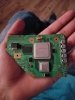
You can always lift the trace cut leg off the pad and solder the wire directly to the leg itself if you're concerned.going to prep the ports for a/v and main power later after i get the voltage readings on these regs. u10 is also soldered in place but I'm still skeptical about the cut trace. if i read the resistors correctly and not like an idiot i should get the voltages spot on (minus 3.3v i got 1.8k)
ill have more to add to this later or tomorrow or something what do you guys think of this i know the quality lacks.. and it doesn't help that the image is mirrored i should fix them.View attachment 9198
ok so i went ahead and did that, ground between the regs and wii make continuity, but the ground pin on the input line doesn't make connection with the ground line on my video input, does that make a problem for my video line?Are you getting any voltage from the 1.15V reg? I would check continuity between the ground on the Wii and the ground on the regulator just to make sure they're connected.
so wait disconnect the regs to the wii and check for continuity with ground and the output lines on the wii? or take the whole component off the board? I'm assuming you're talking about the first option ill be sure to do this when i get off work todayThe 1.15v line often will cause your multimeter to beep for continuity because the resistance is around 30 ohms. This is normal, just make sure it's not less than 10 or so. As for the 1v line, if it is in fact bridged to ground, disconnect it from the board and check if the short is on the board or the regs. If it's on the board, you probably need to sand more.
yesThe 1.15v line often will cause your multimeter to beep for continuity because the resistance is around 30 ohms. This is normal, just make sure it's not less than 10 or so. As for the 1v line, if it is in fact bridged to ground, disconnect it from the board and check if the short is on the board or the regs. If it's on the board, you probably need to sand more.
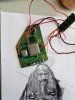
That thick black wire with the yellow mark is the ground connected to one of the pins on the input line from the original Wii port. I assume the grounds are all the same on the av port. And which pin on the u10 outputs 3.3? I know the pin that doesn't run the wire gets continuity with the 3.3v line but I took stitches advice and just bent the pin upwards instead of It being soldered to the pad on the mobo and just ran the wire through, But the wire seems to make connection to the pin without being bridged to any other vias. I was thinking of separating the av and power ports from each other, but I wouldn't believe that to be an issue. I'll shorten the wires, but I started testing with the power mii lite board so I don't understand what you mean by powering them separately, but I'll do that with the custom regs if I still use those for this.Those wires look really long. Try shortening them up. It's also worth disconnecting the voltages from your regs and powering them separately. If you get constant voltage on the regs, then the Wii is the problem. It sounds like the Wii is drawing power though, so make sure your U10 connection is solid and that you're getting ~3.3V out from that as well.
Also, what are you testing the video on? I don't see a ground wire running from the Wii to whatever that composite line is attached to, so that could be your problem as well.