Worklog WiiVision Build

Tron

.
Joined
May 26, 2020
Messages
83
Likes
57
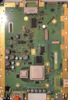
My ten-year-old son recently turned me onto Wii portablizing. After spending days reading various BitBuilt threads, watching Noah’s epic 10+ hour, 2-part YouTube video, and getting a case from the ever gracious Gman, I am starting my WiiVision build. I'll post my progress and share my BOM once I'm further along. In the meantime, because of the unusual trim required for the WiiVisiion case, I want to double check to see if the proposed trim (in the attached photo) based on Noah’s video and ABH’s worklog looks correct to those who have done it. Thanks in advance.
 

Attachments

Gman

RTFDS
Staff member
.
.
.
.
.
Joined
Feb 25, 2016
Messages
1,437
Likes
2,887
Trim looks alright, make sure it's not cutting into the NAND on the back. Once you cut a little and put the shoulder buttons in, pretty easy to see if you need to go any further if it fits or not
 

Tron

.
Joined
May 26, 2020
Messages
83
Likes
57
As I’m installing PortablizeMii on multiple Wiis, I’m wondering if the individual MAC address only affects the content of SD card or the USB’s as well? In other words, can I just copy the newly generate SD content onto the SD card and reuse the same USB content from a prior PortablizeMii generation?
 

Moo

.
Joined
May 25, 2020
Messages
5
Likes
5
As I’m installing PortablizeMii on multiple Wiis, I’m wondering if the individual MAC address only affects the content of SD card or the USB’s as well? In other words, can I just copy the newly generate SD content onto the SD card and reuse the same USB content from a prior PortablizeMii generation?
I believe the SD contents is console dependant, however whats written to the USB drive doesn't matter (the MAC address is only needed for the initial payload aka LetterBomb).
 

Tron

.
Joined
May 26, 2020
Messages
83
Likes
57
Thank you, Moo. I'll give it a try and report back.
 

Tron

.
Joined
May 26, 2020
Messages
83
Likes
57
I finally received my stencil and soldered a PMS board (shown in the attached photo) with a rework station. I have a couple of questions and would appreciate some guidance.

One, I noticed that the photo of the PMS in the BitBuilt store shows the C28 pads with a capacitor and C26 being empty but the BOM in the GitHub lists a capacitor for C26 but nothing for C28. Should I switch C26 and C28 on my board?

Two, I bought a PICKIT3 kit. Where can I find instructions for programming the PMS? How do the holes on the bottom of the PMS board correspond to the pinouts of the PICKIT3?

Thanks.

IMG_1373.jpg
 

Gman

RTFDS
Staff member
.
.
.
.
.
Joined
Feb 25, 2016
Messages
1,437
Likes
2,887
Nice job

C26 and C28 are the same value. It's OK if one of them is not present, no difference.

Download MPLAB IPE, you will select PIC16F15324, select the RVLPMS hex code on the github, connect the pickit (the 5 pin connector on rvlpms is same first 5 pins of the pickit). Then hit program. If it says programming succeed, it's ready to test.
 

Tron

.
Joined
May 26, 2020
Messages
83
Likes
57
Thanks. Is pin 1 the square hole on the left on the bottom of the pms board?
 

Tron

.
Joined
May 26, 2020
Messages
83
Likes
57
I made myself a pin header adaptor and wired up a battery to the PMS as shown in the video. I've soldered two PMS boards. One of them would not program and gave an error: "Target device was not found (could not detect target voltage VDD). You must connect to a target device to use PICkit 3." The second board appears to be programmed and I got a "Programming complete." But when I test the voltage on the 1v, 1.15v, 1.8v, and 3.3v, my multimeter shows 0 volts. The 5v pad shows 151 mv. What am I doing wrong? Thanks!
 

cheese

the tallest memer in town
Staff member
.
.
.
Joined
Mar 2, 2016
Messages
2,759
Likes
2,431
Location
Florida
Did you make sure to plug the charger in momentarily and then hold the power button to turn it on?
 

Tron

.
Joined
May 26, 2020
Messages
83
Likes
57
Thanks, @cheese. Yes. I tried that. It didn't seem to make a difference. I am attaching a photo of the my set up. Since I posted my last question, I tried to reprogram the PMS board that I was able to program before. But this time, I got an error:

Invalid command response (sent 0x41, received 0x3f)
Connection Failed.

IMG_1405.jpg
 

cheese

the tallest memer in town
Staff member
.
.
.
Joined
Mar 2, 2016
Messages
2,759
Likes
2,431
Location
Florida
Could you double check, it looks like there may be a short on U7 on the left side, though that shouldn't prevent you from programming the board... I'll have to look through the documentation to see if I can find something else soon.
 

Tron

.
Joined
May 26, 2020
Messages
83
Likes
57
Thanks. I cleaned the left side of U7 up (see the attached photo), but it did not make a difference. Only the 5v pad shows a .696V. Also, L6 feels pretty warm whenever I connect B+.

S20200704_002.jpg
 

Tron

.
Joined
May 26, 2020
Messages
83
Likes
57
I replaced the PIC on both boards. Now, I'm getting "Target device was not found (could not detect target voltage VDD). You must connect to a target device to use PICkit 3." for both boards even though the boards are connected to a 3.7V battery source. I'm really at a loss here. Any suggestions for how to debug this thing would be greatly appreciated.
 

Gman

RTFDS
Staff member
.
.
.
.
.
Joined
Feb 25, 2016
Messages
1,437
Likes
2,887
It is probably issue with soldering. Observe each pin and pad to verify it is making connection to pcb and not shorting to something next to it where it shouldnt be.
 

Tron

.
Joined
May 26, 2020
Messages
83
Likes
57
Thanks, @Gman. When you say issue with soldering, are you referring to the PIC specifically or just generally to any components on the board?
 

Gman

RTFDS
Staff member
.
.
.
.
.
Joined
Feb 25, 2016
Messages
1,437
Likes
2,887
Thanks, @Gman. When you say issue with soldering, are you referring to the PIC specifically or just generally to any components on the board?
The whole board. Every chip and component.
 

Tron

.
Joined
May 26, 2020
Messages
83
Likes
57
Thanks. Since I have extra PMS PCBs, can I just solder the PIC to U6 on an empty board and power up with a battery to program the PIC?
 
Top