Updates, updates, updates! I am currently working hard on finishing the second revision of the PCB!
Today was mostly spent using tRestrict, setting the grid to a very small value and having fun neatening up all of the messy polygons. Thanks to YveltalGriffin for suggesting this idea! Although it does not really impact the functionality of the board, it gives it a nice personal touch and makes the board look a lot neater than the auto-generated ground/power fills EAGLE generates for you.
But, actually, speaking in truth, nothing much has changed from the previous revision in terms of what components are included on the board. I have included an SD reader IC that will allow me to seamlessly read the onboard Micro SD card. The SD card will be accessible and removable easily by pressing on the SD card (i.e a spring loaded card) so that I can easily update the Micro SD whenever I feel like that be necessary. Sometimes, in my portables, I have put a smaller 128GB card and wish I was able to easily update it to a larger card to hold more games. Well, this will now be achievable thanks to the IC! The SSOP package is designed in such a way that the peripheral components can be placed close to the IC pins in a large capacitor/resistor "bank" so to speak. It is a little cramped since I am using 0603 packages, but this will make it easier to assemble of course. It also came in a larger QFN package as well which might have saved me some space, but the SSOP package works nicely for me I guess.
I also ended up replacing that horrific potentiometer from Digikey (yeah, they don't have many good volume wheels to be honest) that was in the previous revision with something with a much bigger radius but thinner profile. This hopefully will make it easier to turn. I am aiming for the feeling of a GameBoy color feeling volume wheel that is really smooth and pleasurable to turn... uhh... on... and off
")
Here are some more pictures of the PCB so far. I want to wait a good month before ordering this time to triple check the schematics again and make sure there is no mistakes like last time. As you can see, the routing/planes are a lot neater than the previous revision, and everything has more breathing room compared to before which is a great improvement. The TPS regulator modules are so great, hopefully they are not too difficult to solder into place since they are not QFN but rather a uSIP package.
Here is the top half of the board. This houses the USB-C (still using the STUBS4500) and Gmans power profile code. I plan on porting this over to Jeff's code once I get an opportunity, though. As you can see, there are a lot of vias, with the VBUS signal being connected entirely with a large power plane and several stitching vias. This made it a lot easier to fit the components into a small area of board. The USB data switching and card reader dankness is on the left hand side there (look at all those caps/resistors...) Luckily, they are as close as possible to the chips input/output pins. The GL827L has an onboard 3v3 stepdown regulator and is powered entirely from 5v, so I didn't need to change anything with my switching circuitry/power the card on a separate 3v3 LDO regulator or something. This allowed me to easily incorporate it into the design, without changing much at all (the previous rev used a generic USB-A port which was huge and added a lot more height). I will be able to shave off a couple mm of case thickness now, too!)
View attachment 13965
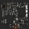
Here is the RVL-PMS, running the BQ25895M controlled over i2c in combination with the newer (to me, at least) fucking awesome TPS regulators. More stitching vias were used here to connect everything. I made sure to pull 3v3 and 1v8 signals for the U-AMP/GC+ from the bottom of the board (i.e routing them downwards) so as to not cut into the VSYS plane. It is important so that everything can breathe well on the board and there be no bottlenecks for the current to flow to where its needed. I think it looks really good for a noob like me! Without Yveltal, this wouldn't be looking as nice as it is now - a big thanks to him for always teaching me more about PCB layout and giving me little hints along the way (still have a long way to go, though... ). For now, the BQ25895 is great, but I'd like to try and use a different charging IC next time for higher voltage inputs so I can use my switch charger (saving me having to carry two chargers around in my backpack when I'm on long business trips or whatever).
View attachment 13964
Finally, the GC+ from Pizza Lord, LM49450 (Gman) and some poorly placed FFC connectors which are now finally on the top of the PCB instead of the bottom (what the hell was I thinking last time?) They are not in the most convenient locations (i.e I will have to fold over the ribbon cable for the bottom connector for it to work) but I know that they will fit in these positions from the last revision at least.
View attachment 13962
Finally, the entire PCB - top and bottom so far (you might have noticed I made it more "square-looking" compared to last time - there was a lot of wasted space on the previous board that I could have used, given that there was plenty of space in the case for the PCB to be wider/longer. I added some nice silkscreen I guess, some personal aesthetic if you will


. Finally, one huge issue I noticed last time was that it was very difficult to get the external components like the USB-C port, volume wheel and on/off switch to fit last time, mainly because the holes were only located in the top half of the base of the portable. This time, in order to machine it, I have made sure that the two halves of the case will fit nicely over those parts instead of having to solder them all whilst the PCB is in the portable. Might be obvious to most, but I overlooked it initially for my contest build (also this is required in order to be able to CNC those parts!)
That's all for now. Hope this wasn't too long, but I'm still excited and morale is high! Can't wait to get started on it again in the flesh soon.
View attachment 13963View attachment 13961