
Worklog The Wii SPii
- Thread starter StonedEdge
- Start date
Thanks, I used some chipquik TS391AX50 solder paste along with 360 degrees on my hot air station and a stencil to assemble the board.Your soldering looks great. I’m just learning to use the hot air gun reflow method to solder the SMDs. May ask what kind of soldering paste and hot air gun temperature you are using to mount the SMDs?
Yeah, 360C. Check the datasheet for the solder paste you are using, it will show you the melting temperature. This particular one melts at around 183c, but I usually use a higher heat anyway and haven't had too many problems with killing any ICs or anything.I clicked on Post too quickly. I meant to ask is that 360 F or C?
If you have a reflow oven you can follow the recommended profile but it's not strictly required:
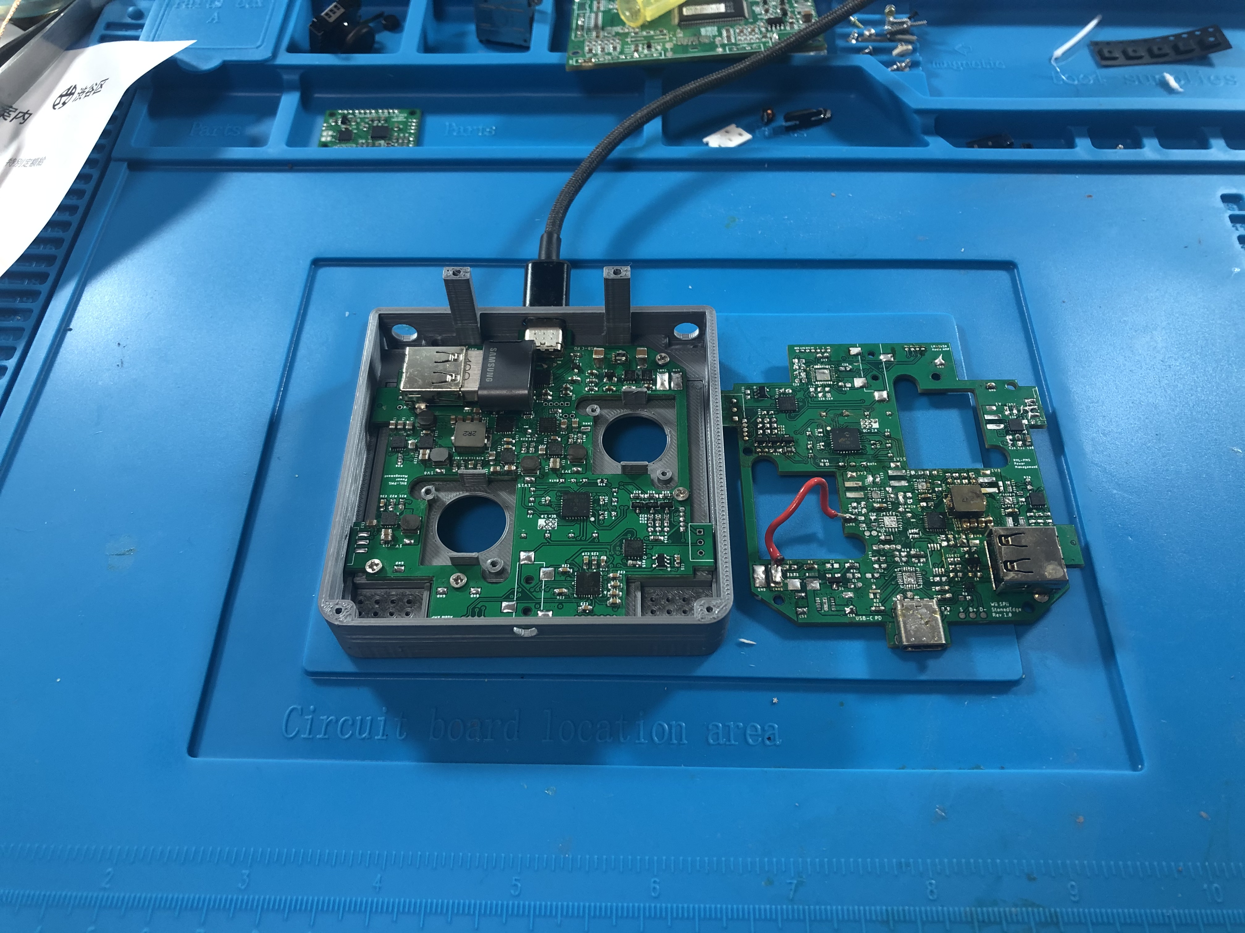
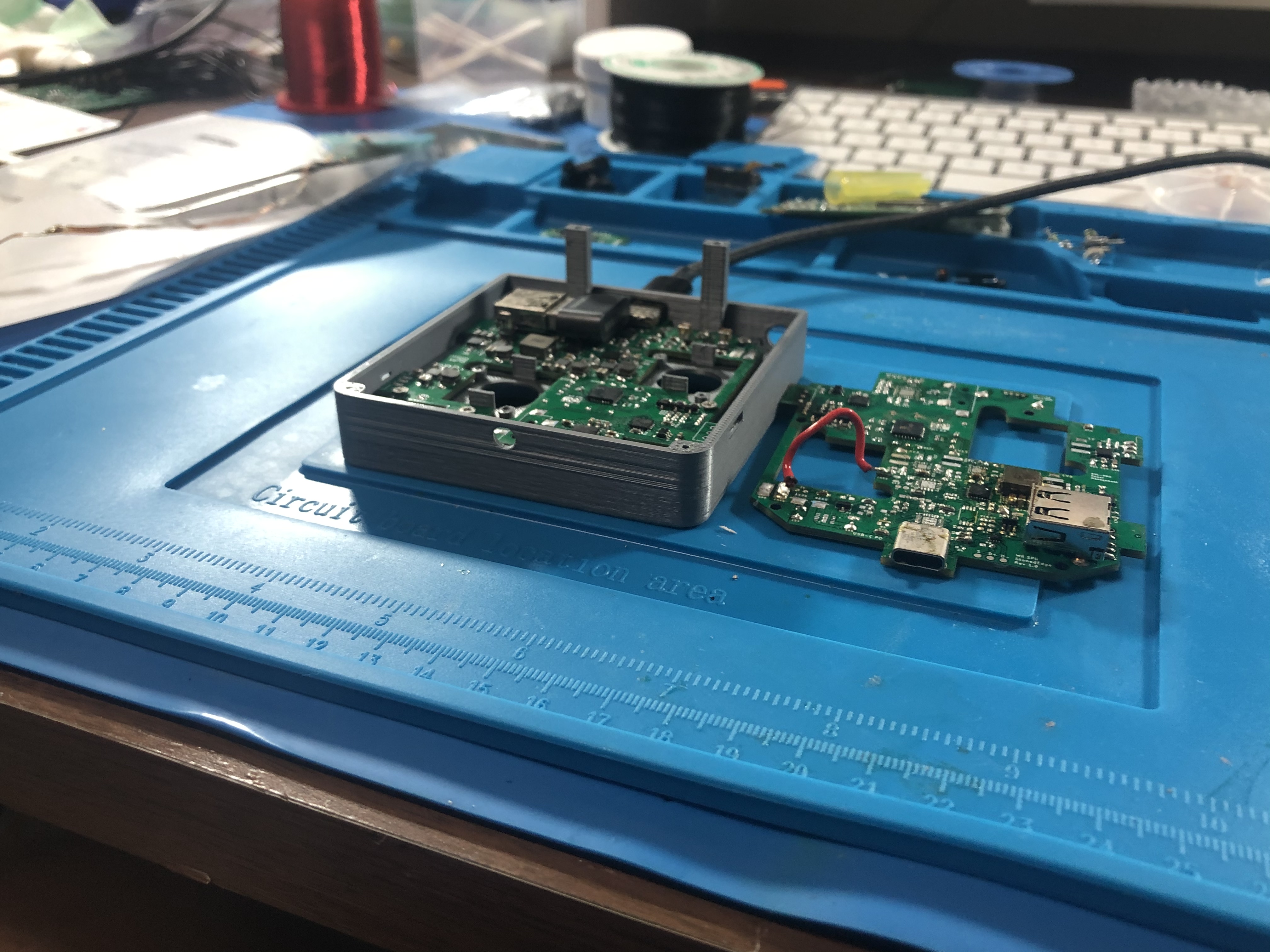
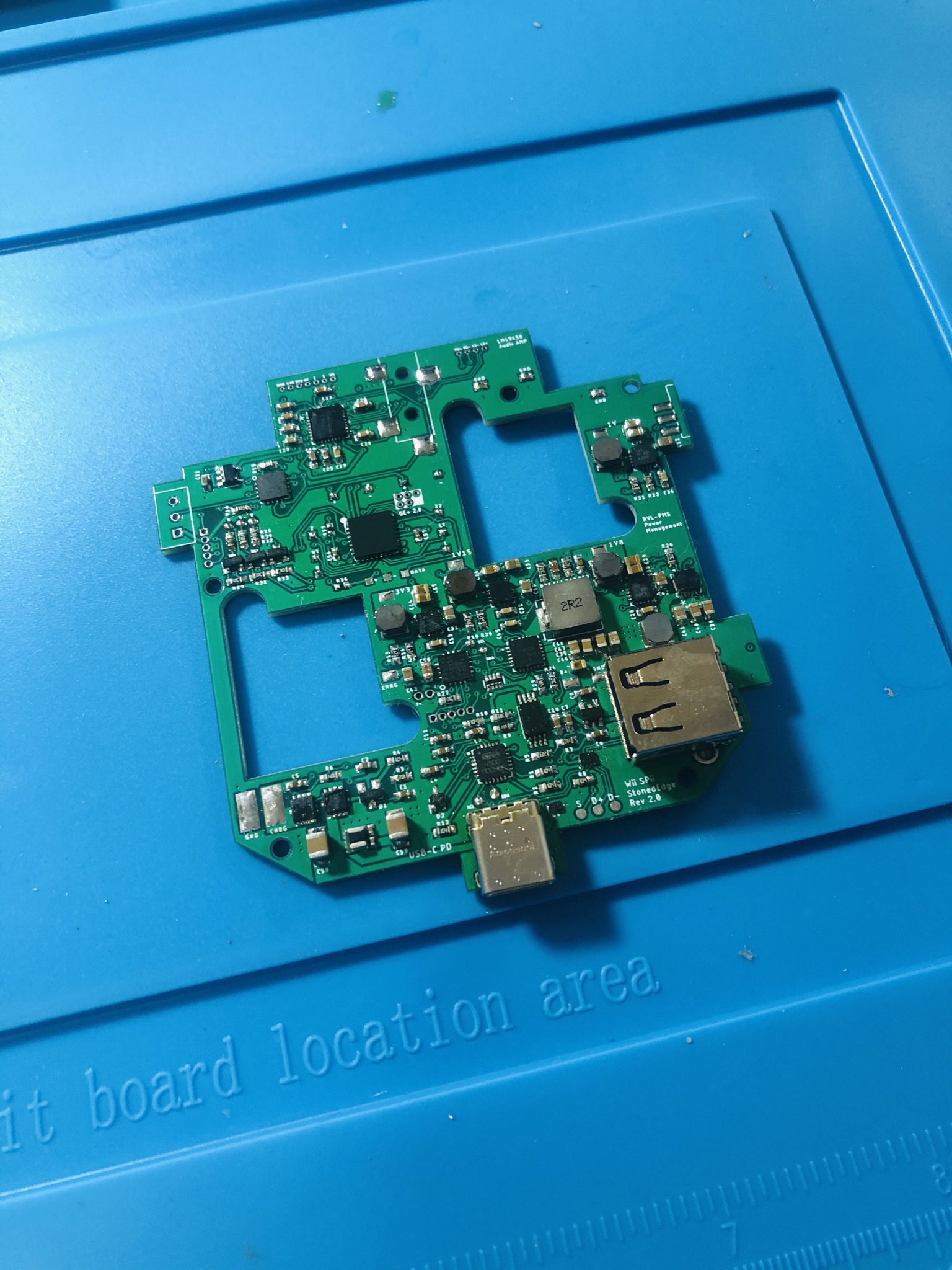
Today I spent a few hours transplanting old components onto the new board I got from JLCPCB. I was able to verify a PD handshake with the STUSB4500, program the NVM and also successfully switch the data lines to get access to the internal flash drive. The nice thing this time is that I actually did some research about USB 2.0 routing, and made sure that I had the microstrip with differential impedance of around 90 ohms/45 ohms SE. My first board involving data lines was a mess, it took over 3 minutes to transfer a 1GB game. This time it really only took 30 seconds for a transfer of the same file, so improving the routing really helped me roughly get 35MB/sec approx. It was definitely nice to have a 4 layer board to route these lines as well.
Of course USB 2.0 can be done on 2 layers, but the problem with that on this board is that the traces need to be quite a fair way apart to get the impedance requirement we need, and as you can see I don’t really have the space since the PCB is already really dense. The thicker core of a 2 layer results in a much higher impedance than a 4 layer, but because the prepreg layers can be a lot thinner with 4 layers you get much higher capacitance as the copper layers are generally much closer together. Here’s the calculator I used. You’ll want to use the Differential Microstrip Impedance Calculator to make sure you maintain the signal integrity rather than just routing them like other traces. One last tip would be to avoid cuts in the ground plane below the pair. It’s a bit easier to do with a 4 layer board since you have the internal voltage and GND layers, but splits in the planes below the traces can really slow down the transfer speeds (speaking from experience). Here is a good calculator I used. https://www.mantaro.com/resources/impedance-calculator.html
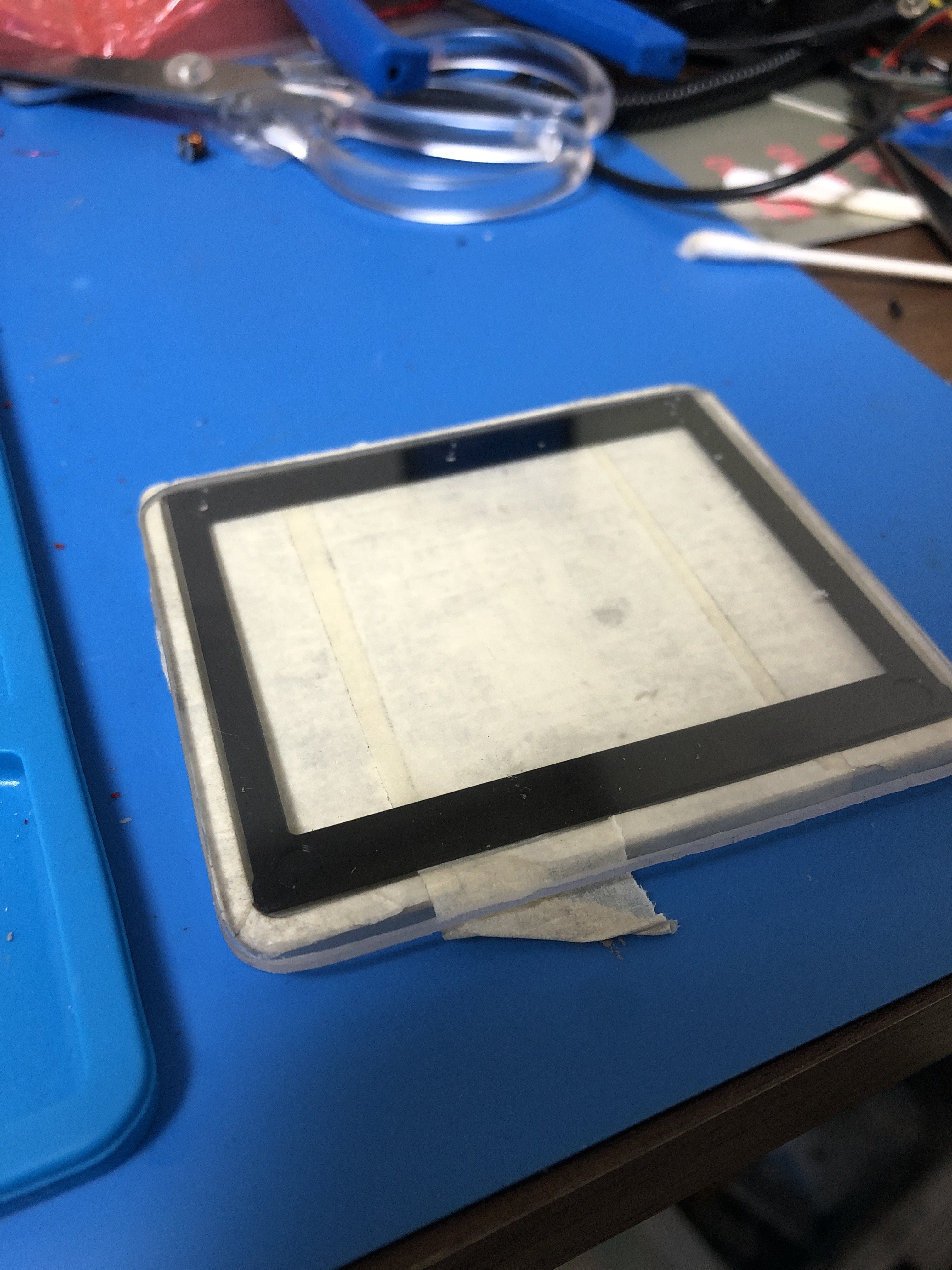
Tuesday I will take a Wii with me to a local workshop and test the regulators to hopefully get an OMGWTF Wii working I also bought myself a couple of 27Mhz crystals to try for my screen driver board, as well as some smaller profile ferrite inductors for the backlight boost converter. I wasn’t sure on the load capacitance for the crystal, so I just ended up getting an 8pf crystal along with two 8pf capacitors to replace the ones currently on the drive board.
Of course USB 2.0 can be done on 2 layers, but the problem with that on this board is that the traces need to be quite a fair way apart to get the impedance requirement we need, and as you can see I don’t really have the space since the PCB is already really dense. The thicker core of a 2 layer results in a much higher impedance than a 4 layer, but because the prepreg layers can be a lot thinner with 4 layers you get much higher capacitance as the copper layers are generally much closer together. Here’s the calculator I used. You’ll want to use the Differential Microstrip Impedance Calculator to make sure you maintain the signal integrity rather than just routing them like other traces. One last tip would be to avoid cuts in the ground plane below the pair. It’s a bit easier to do with a 4 layer board since you have the internal voltage and GND layers, but splits in the planes below the traces can really slow down the transfer speeds (speaking from experience). Here is a good calculator I used. https://www.mantaro.com/resources/impedance-calculator.html
Tuesday I will take a Wii with me to a local workshop and test the regulators to hopefully get an OMGWTF Wii working
I also bought myself a couple of 27Mhz crystals to try for my screen driver board, as well as some smaller profile ferrite inductors for the backlight boost converter. I wasn’t sure on the load capacitance for the crystal, so I just ended up getting an 8pf crystal along with two 8pf capacitors to replace the ones currently on the drive board.
Last edited:
Nice work, and very cool that you did your research on impedance. Another note to add is whenever you change layers on an impedance controlled signal you should place symmetric ground vias next to the signal vias to preserve integrity when traveling along the z-axis. Board is looking great!
Thanks Jeff! I actually didn’t know that at all, so thanks for clearing that up. I actually did have to use vias because of the arrangement of the data lines from the TS3USB IC to the USB drive. I tried to avoid it but it wasn’t really possible. Will keep that in mind for next time!Nice work, and very cool that you did your research on impedance. Another note to add is whenever you change layers on an impedance controlled signal you should place symmetric ground vias next to the signal vias to preserve integrity when traveling along the z-axis. Board is looking great!
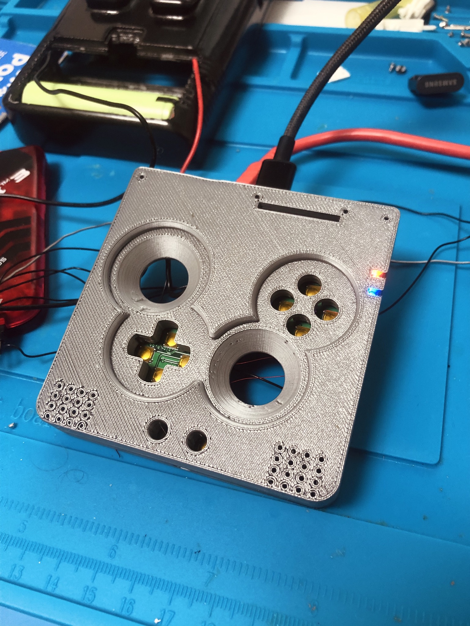
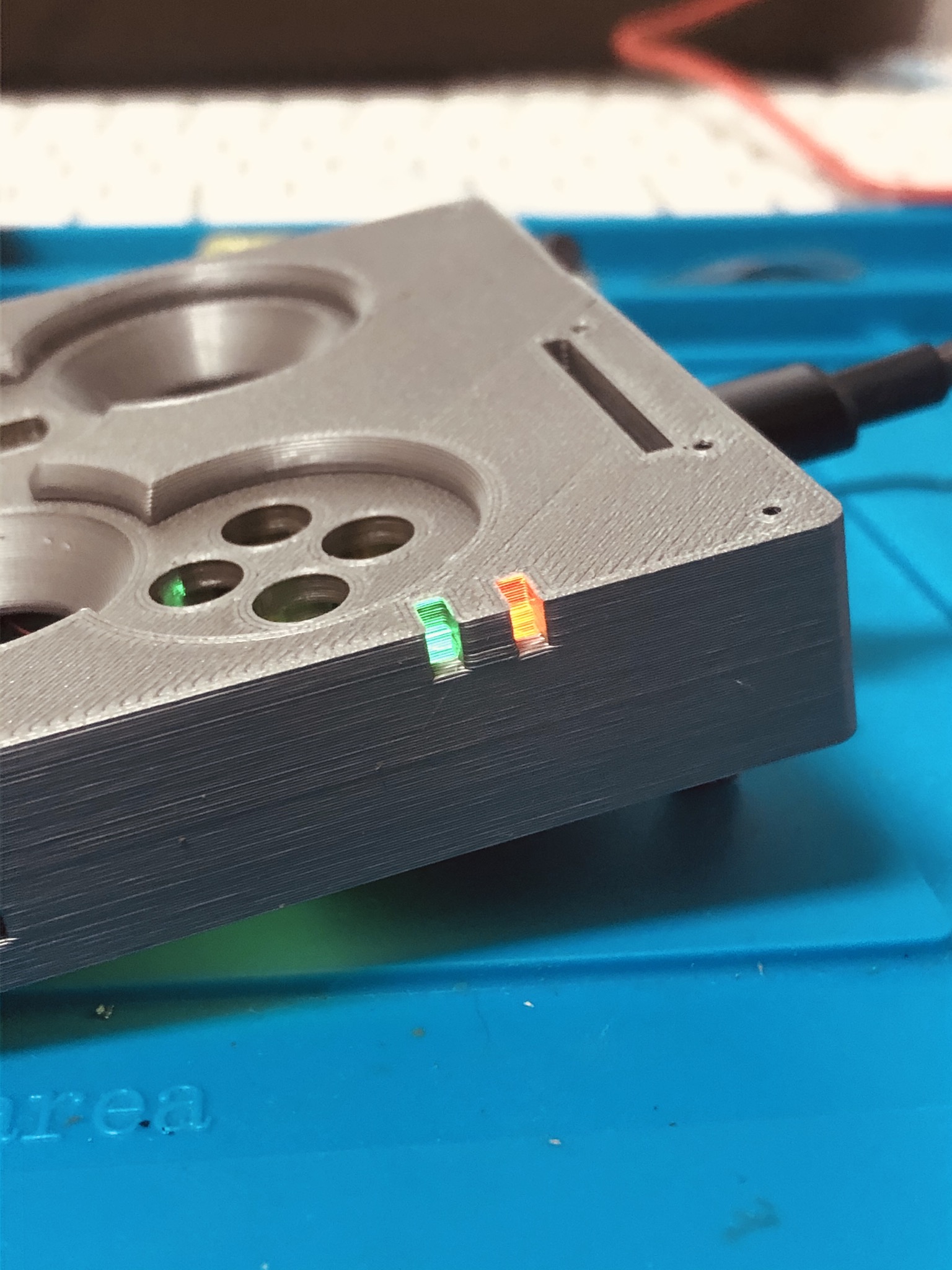
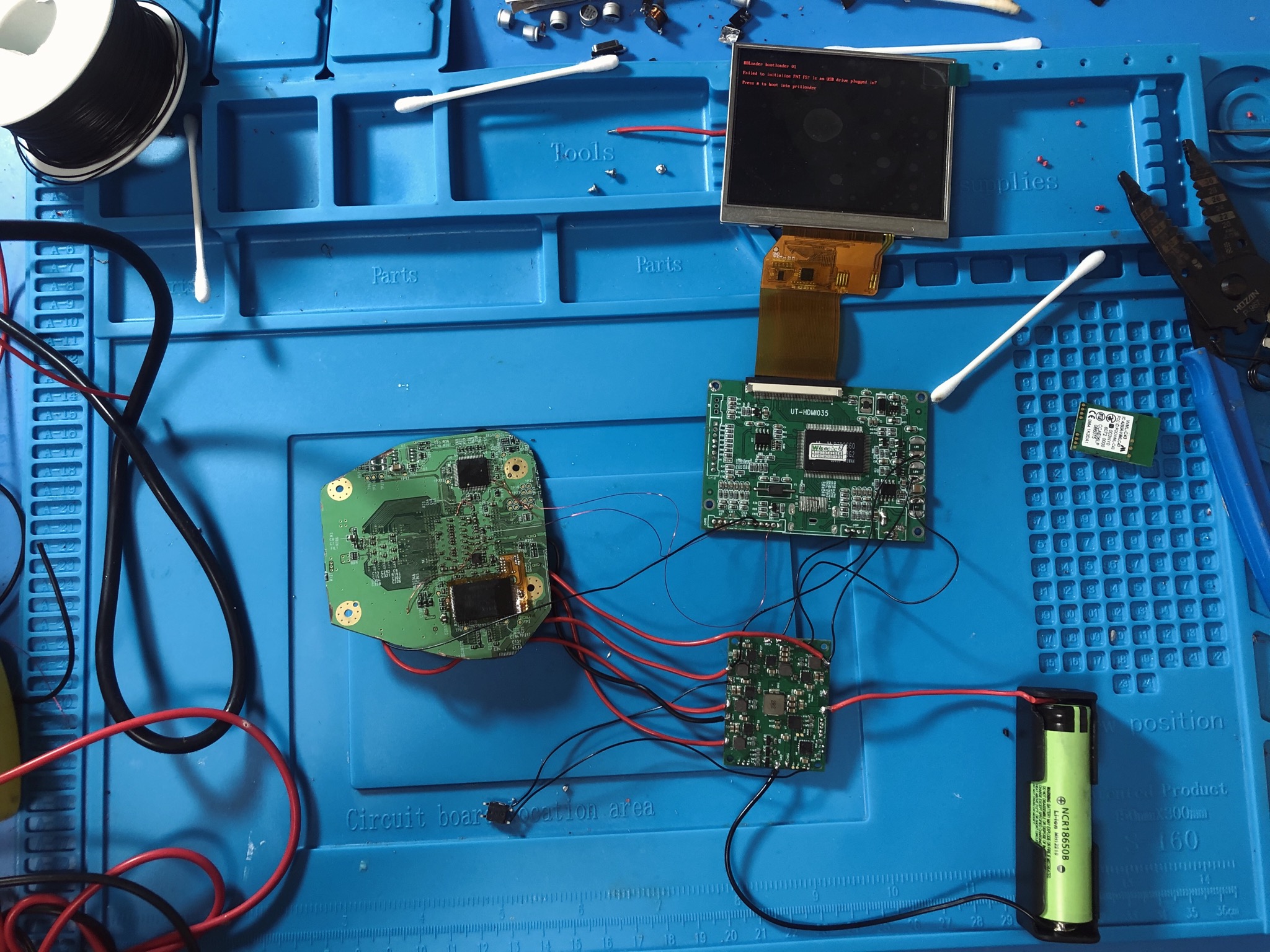
Thanks to some help from the BB team (awesome!) the PCB is confirmed working for the Wii SPii. All regulators output correct voltages, charging is confirmed, digital audio, PD negotiation, data switching, power/low battery LED/charging LED and GC+ 2.0 all confirmed working. Finally time to start putting this together after 4 months of hard work, a board screw up amongst other things. Can’t thank you all enough!
(Just realized that the LED for power on the SP is green
 ). Luckily I used an RGB led for that so I can change it in software easily. The LED turns red when the battery is low to warn the user, similar to the PMS in the store. I also set up PWM on RA2 so I can adjust the brightness without changing the value of the current limiting series resistor.
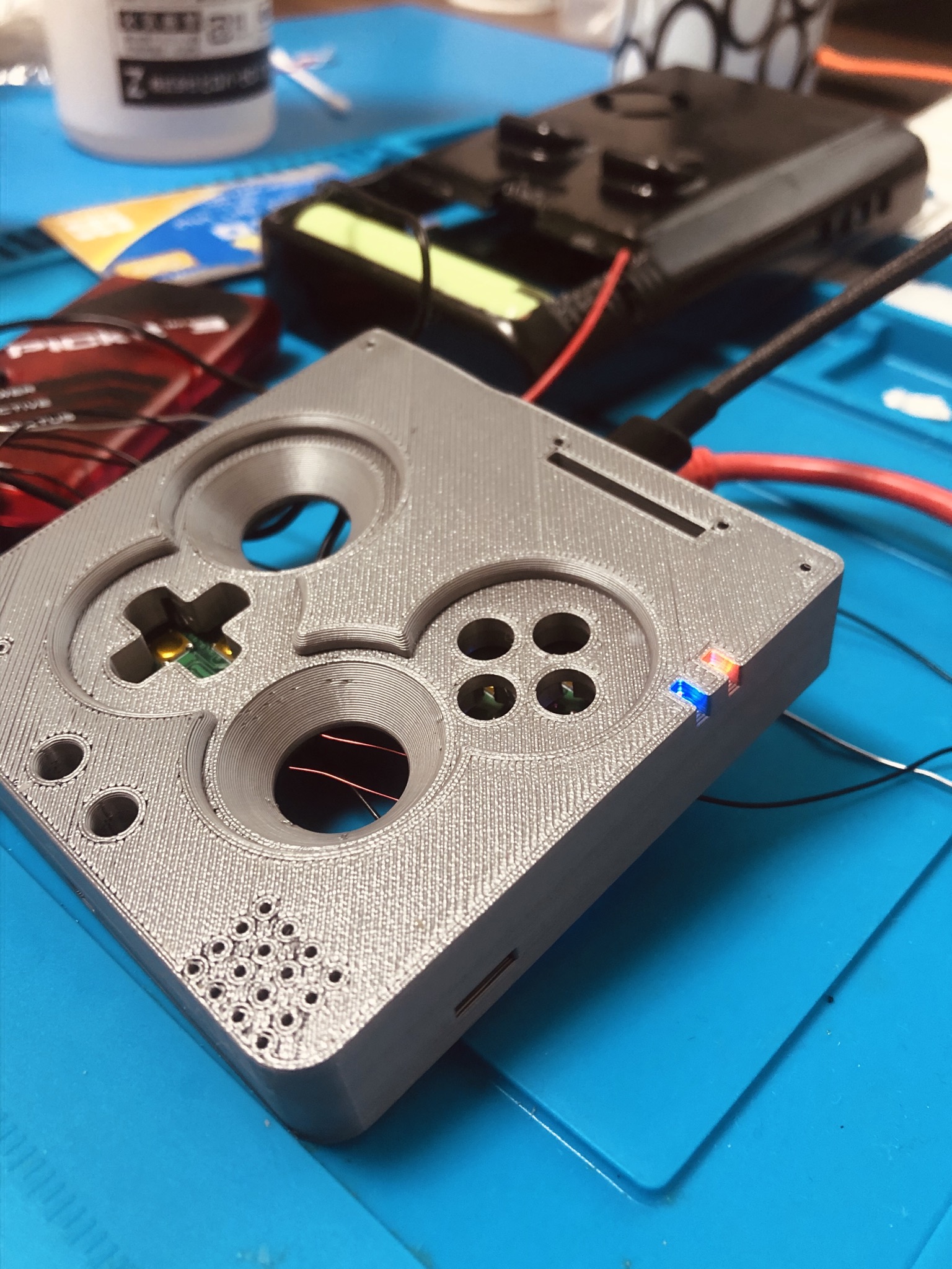
EDIT: Changed it to green now for power indicator.
(Just realized that the LED for power on the SP is green
). Luckily I used an RGB led for that so I can change it in software easily. The LED turns red when the battery is low to warn the user, similar to the PMS in the store. I also set up PWM on RA2 so I can adjust the brightness without changing the value of the current limiting series resistor.EDIT: Changed it to green now for power indicator.
Last edited:
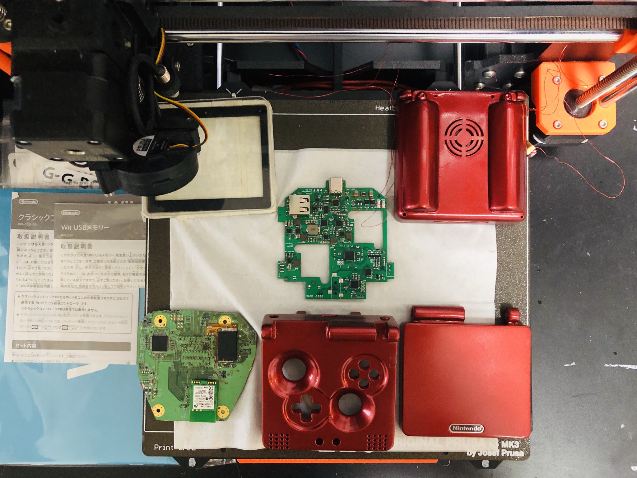
Aluminum anodized faceplate, as well as acrylic machined diffusers arrived today in the mail so of course here is the obligatory show off of both! They look great. Now that I have all of the parts (except for the LMAO trim done) it is time to start building

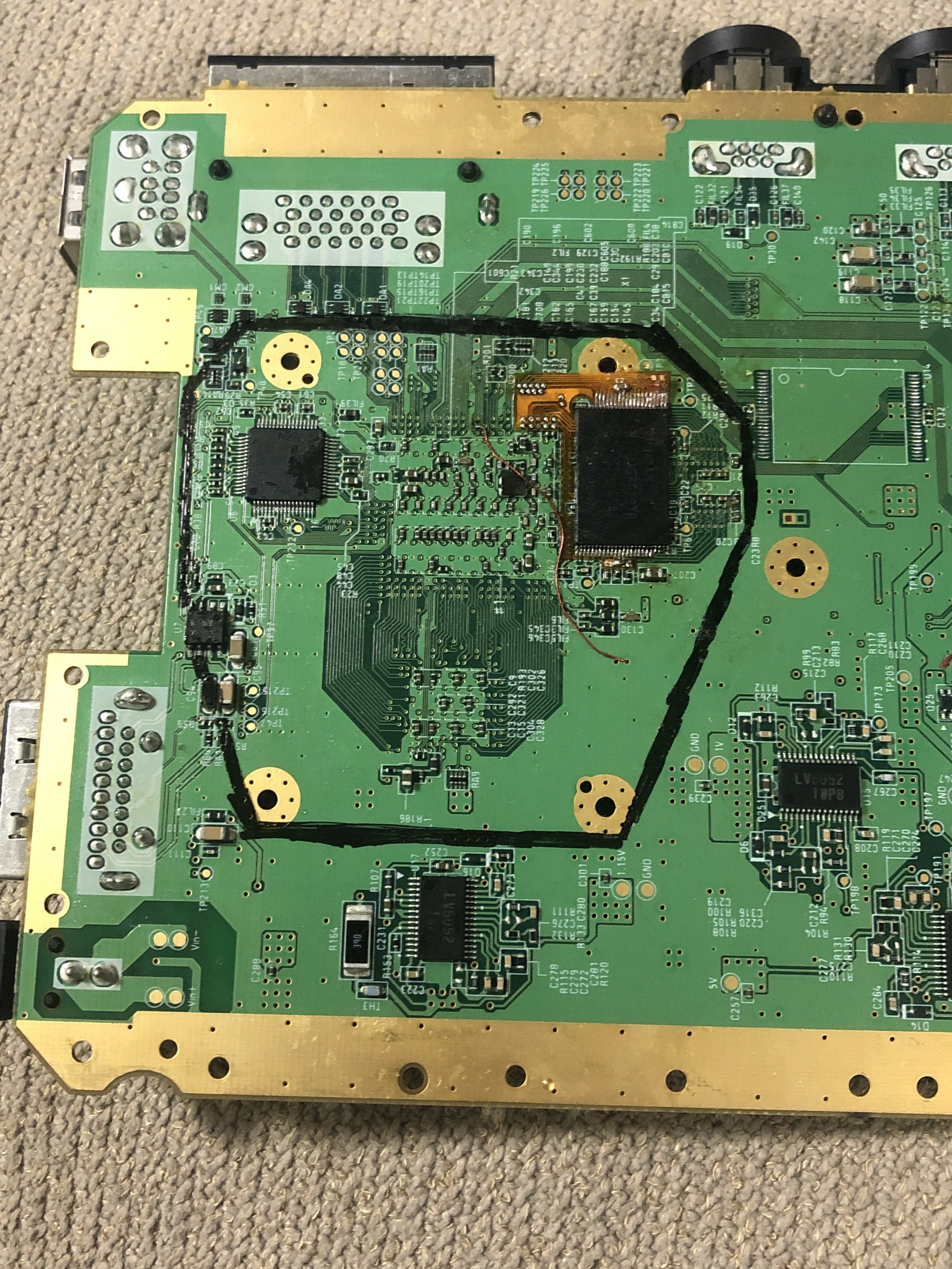
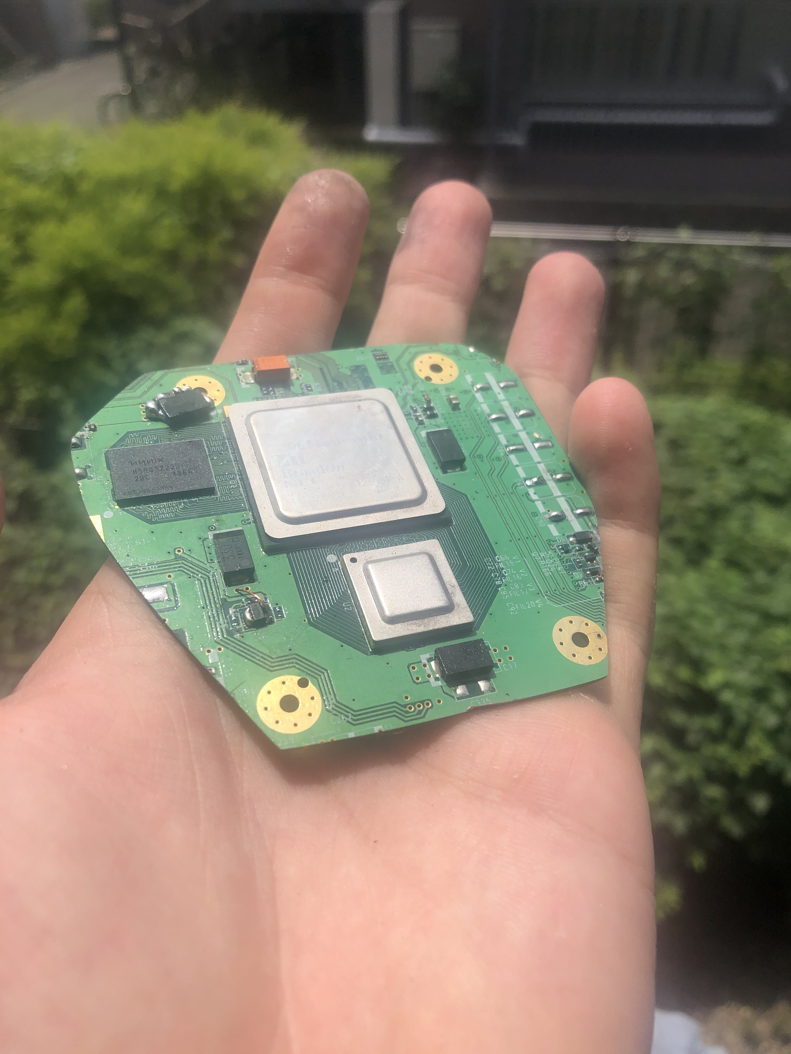
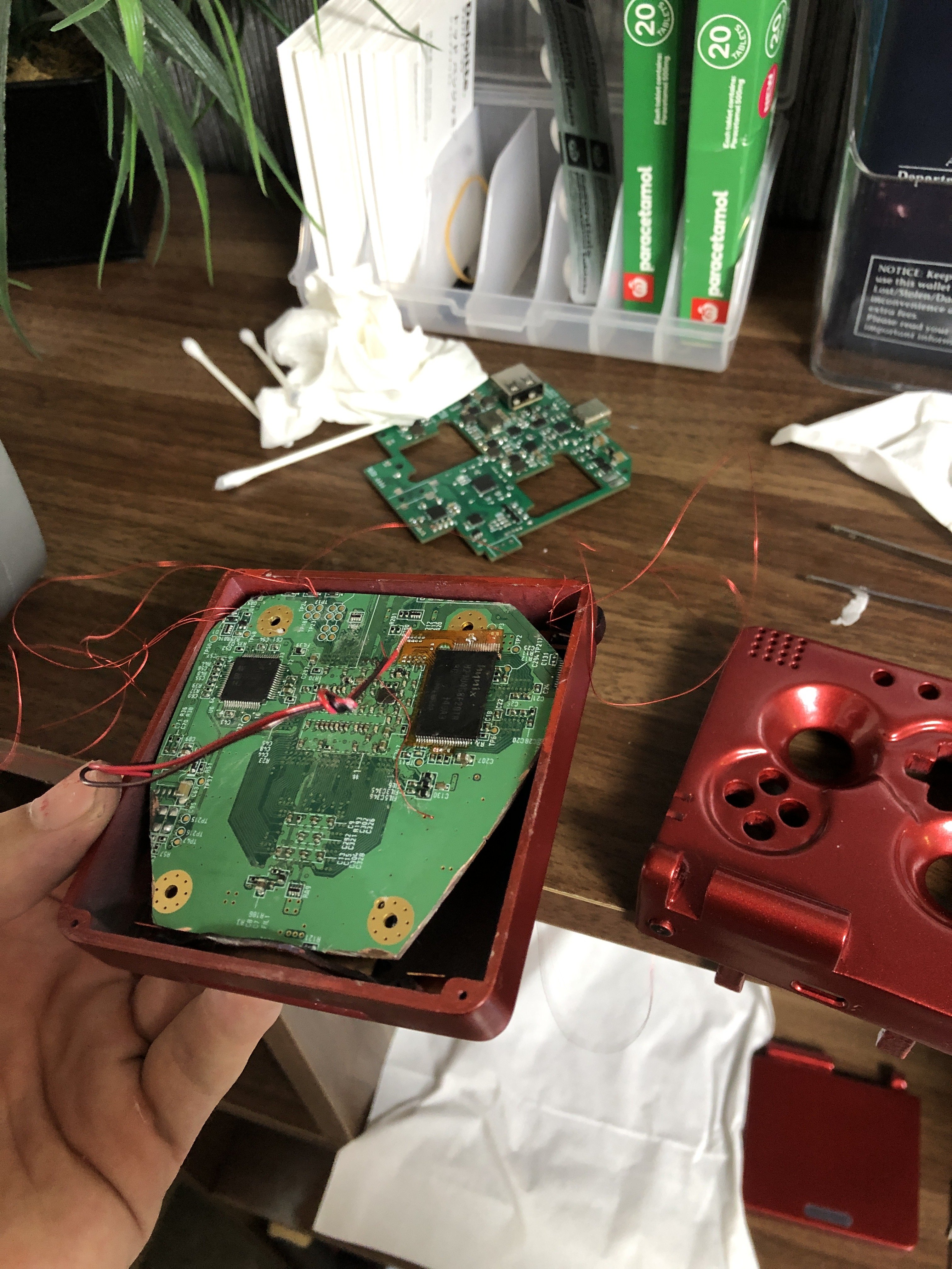
Trimmed my own LMAO trim after verifying that the NAND relocation worked after a few hours of troubleshooting. The flex boards are indeed awesome. The OMEGA definitely wasn’t necessary! A LMAO fits perfectly inside an SP shell as you can see below. I plan on adding some screw posts to the battery covers so that I can remove the Wii easily without using any epoxy or thermal adhesive as I originally planned.

Last edited:
After debugging one of the nand pins that came loose during trimming...
Pizza MEMES coming through with the absolute flex!
First LMAO trim —> success!
Sorry for the double post, but the trim works, I feel like crying I’m so damn happy lolol. Hallelujah baby.
I know that the Wii has been portablized to death, but it's still always satisfying for me to see that we can trim it this far. I am also glad I didn’t use Yveltals OMEGA, which still makes me eligible for the contest. Will have to use that in something else hehe
Obviously OMEGAs are much more impressive, but it is still a great feeling to take a dremel to a mobo and have it work after chopping it up. Wiild.
Time to stream!
Last edited:
- Joined
- Apr 12, 2020
- Messages
- 207
- Likes
- 235
Great job! Been looking forward to seeing this completed. Looks super clean ") .
.
.So this was a bit of a nightmare weekend from hell for me... ")
I was planning on streaming with YveltalGriffin this weekend for everyone to see the build process, but my iMac’s backlight boost converter decided to die and well, that put a dent in our plans... and my wallet... ooft.
I also heard that the 2013 models and later iMacs have all the circuitry (including the backlight booster) on the main logic board as the GPU/CPU etc, which means that I’d have to replace essentially the entire PC main logic board, (unless there was a replacement IC for that...). The iMac is just a disaster to disassemble as well, the front panel is held on with double sided tape, and well I just really don’t want to mess with it, so I decided to buy myself a new Dell XPS
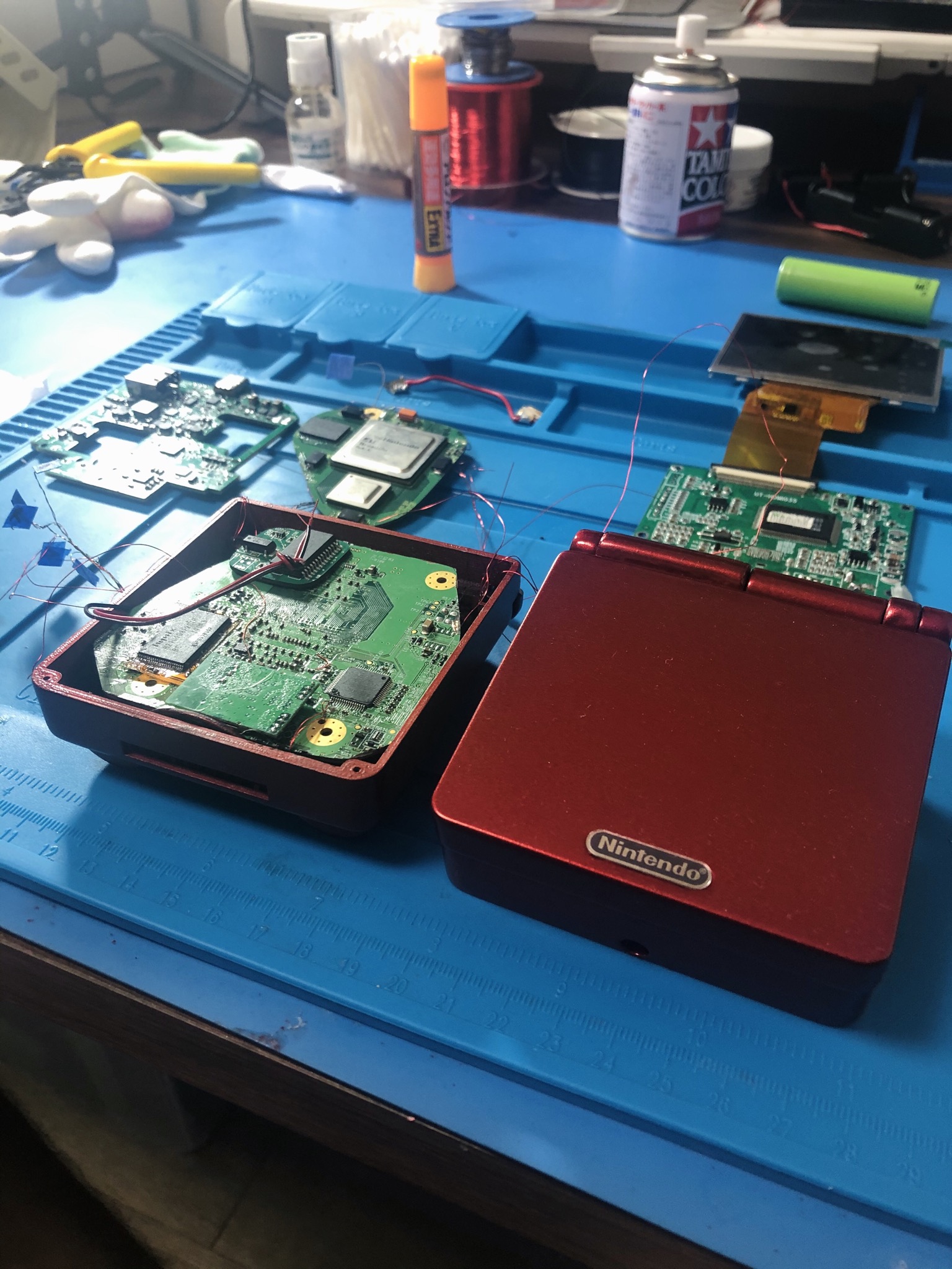
Despite that, I soldiered on (as us contest participants must do!) and decided to get a good chunk of the assembly out of the way this weekend. The batteries fit perfectly below the Wii and the whole thing is just coming together really nicely in my opinion. I’m super pleased of how easy the assembly is after already testing the main logic board. Yeah, it’s not a wireless portable like Jeff, but it’s good enough for me
It isn’t near finished yet but at least you can get an idea of how it is going to look inside from these pictures I hope. It’s not a stream like I had originally planned for everyone, but I hope the NSFW nudes are good enough for y’all. I am sure I will make a Rev 2 edition shorty after, this already has many flaws that I have noticed throughout the assembly... nevertheless, nudes!
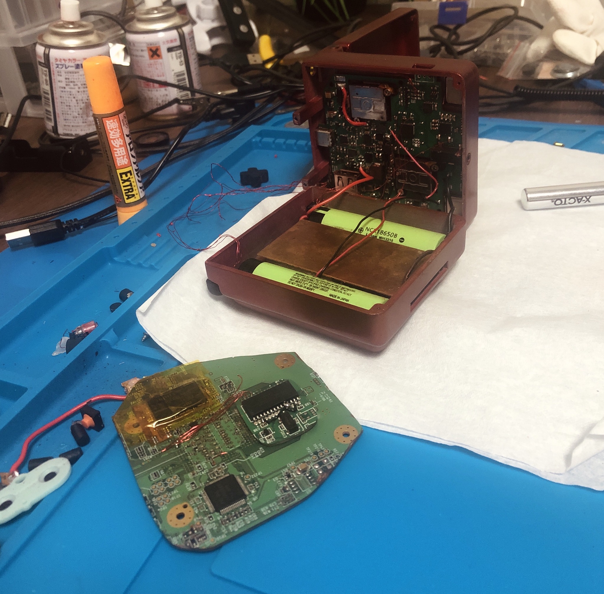

I was planning on streaming with YveltalGriffin this weekend for everyone to see the build process, but my iMac’s backlight boost converter decided to die and well, that put a dent in our plans... and my wallet... ooft.
I also heard that the 2013 models and later iMacs have all the circuitry (including the backlight booster) on the main logic board as the GPU/CPU etc, which means that I’d have to replace essentially the entire PC main logic board, (unless there was a replacement IC for that...). The iMac is just a disaster to disassemble as well, the front panel is held on with double sided tape, and well I just really don’t want to mess with it, so I decided to buy myself a new Dell XPS
Despite that, I soldiered on (as us contest participants must do!) and decided to get a good chunk of the assembly out of the way this weekend. The batteries fit perfectly below the Wii and the whole thing is just coming together really nicely in my opinion. I’m super pleased of how easy the assembly is after already testing the main logic board. Yeah, it’s not a wireless portable like Jeff, but it’s good enough for me
It isn’t near finished yet but at least you can get an idea of how it is going to look inside from these pictures I hope. It’s not a stream like I had originally planned for everyone, but I hope the NSFW nudes are good enough for y’all. I am sure I will make a Rev 2 edition shorty after, this already has many flaws that I have noticed throughout the assembly... nevertheless, nudes!
Last edited:
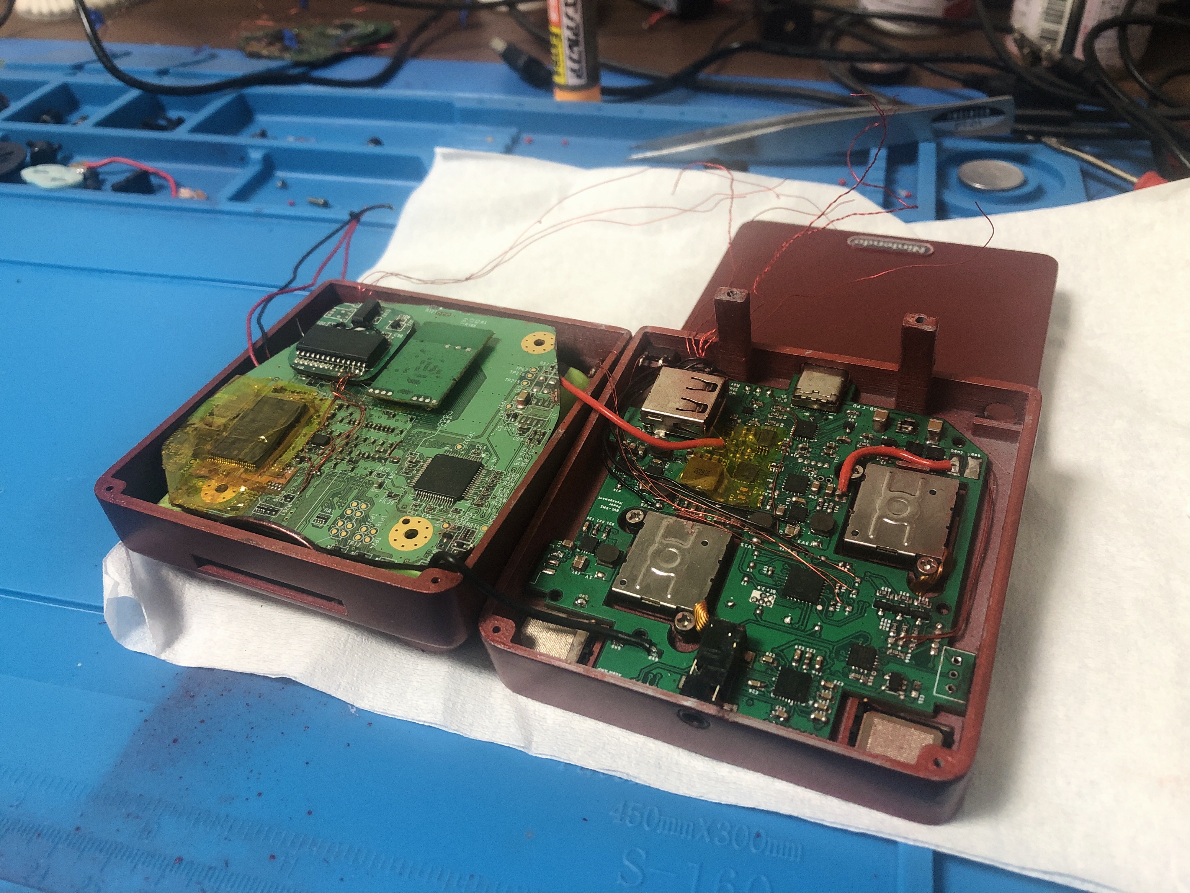
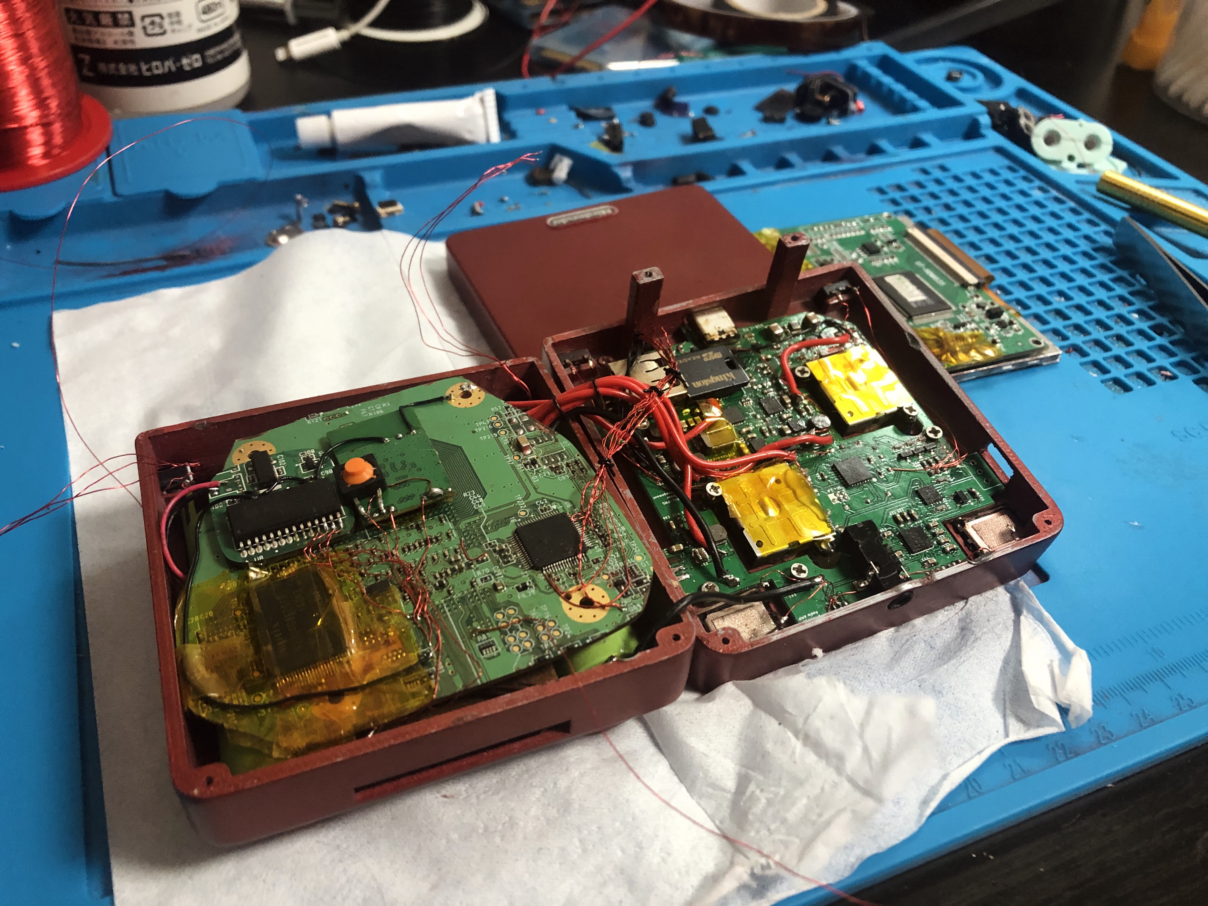
Thanks to BocuD for hosting the stream tonight. 9 hours later and this is how far I got. Hopefully I can close it up tomorrow. A lot of case flaws that I have noticed whilst building that will hopefully be fixed with a revision 2. It’s not as perfect as I would’ve liked but it’s fully functional and I think the wiring is not half bad for a first revision given it’s small size!
You can check out the stream here!
Current state of the Wii SPii. To be continued...
You can check out the stream here!
Current state of the Wii SPii. To be continued...
THE HYPE IS REAL
It'll feel like the end of an era when this is finally completed.
NOTE:
The SPii Rev 1 is dead - rebuilding this entirely from scratch now, both CAD model and PCB.
After 8 months, she’s finally complete.... it died : (
It is actually surprisingly comfortable given the nice grips!). It’s 2am here now, so I am going to sleep, but I will make a video later next week for the contest. I lost my little power switch but I’ll add that after I 3D print/get another one made.
I have to give my thanks and gratitude (a huge thanks, actually) to everyone who gave me advice here and there when I asked and was really stuck. I’ve said it before but the community here rocks. Bob, Gman, BocuD, Ginger, Yveltal, Jeff and of course Aurelio, this is much as your portable as it is mine! It feels awesome to have completed a portable that I can call my own (not a Gboy/G-Wii like I usually build). I learned a lot during this project and without you all it wouldn’t have been possible to keep the motivation levels high, so I thank you all. There are a lot of flaws in this revision that need fixing, but I do plan on open sourcing it maybe a few months later down the track once I make all of the necessary changes. I will mention the flaws in the contest video submission.
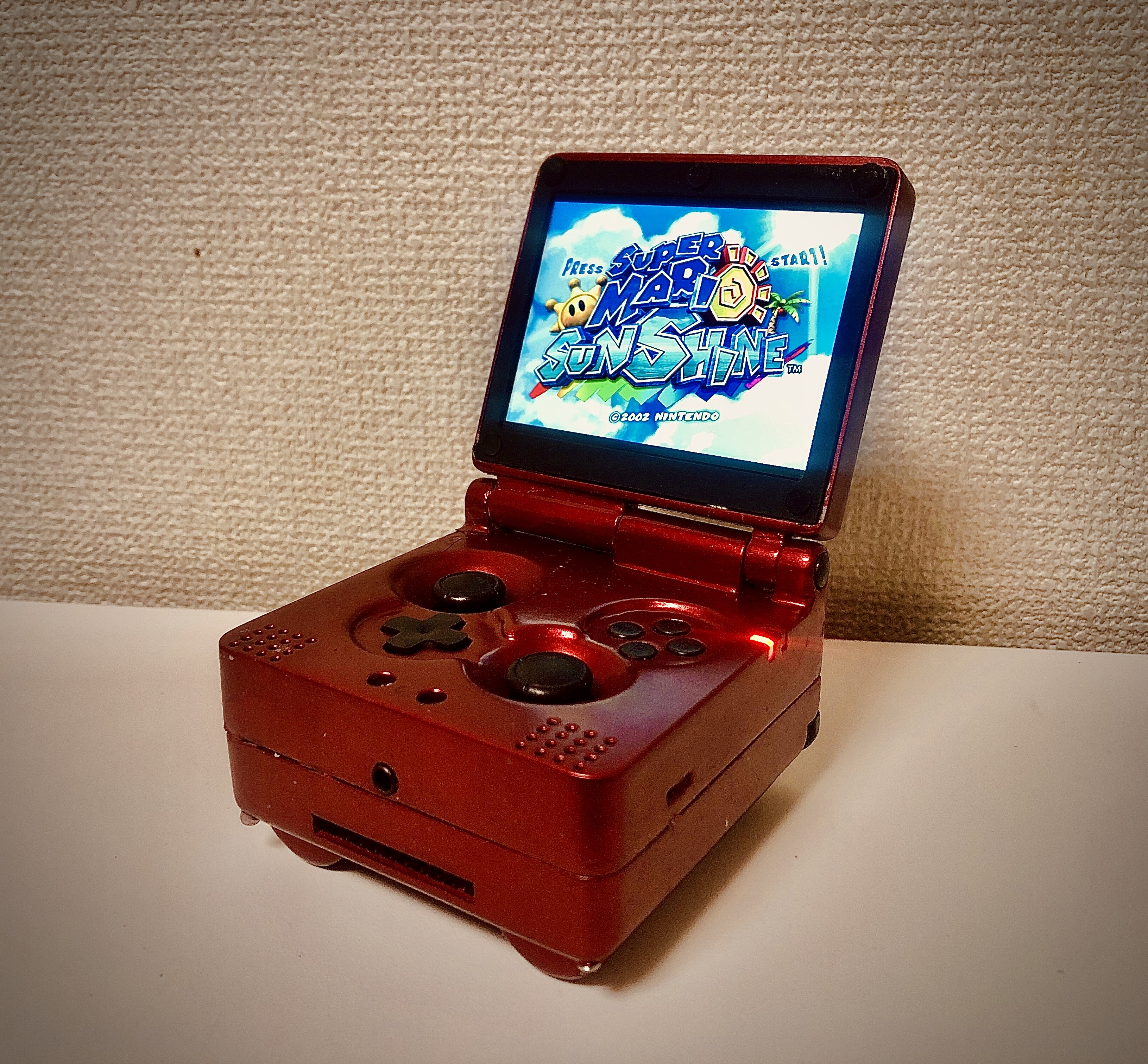
Without further ado... here she is! Introducing my first portable (designed by me, can you believe it isn’t a clone?)
The Wii SPii (2020 Summer Contest) by StonedEdge
Features/Design:
- Full clamshell design
- Wii in an SP form factor (Final dimensions 84 x 82 x 37mm)
- Tamiya pure metallic red finish with black accents
- All-in-one 4 layer PCB from JLCPCB, featuring GC+ 2.0, Wii PMS, U-AMP, USB-C PD
- Overheating protection
- Crystal clear digital audio, adjustable via logarithmic potentiometer (Controlled over the PICs onboard ADC module)
- 640 x 480p VGA 3.5” display (incredible)
- Battery grips x 2 (Panasonic 18650 cells, 3400mAh) - hopefully 2.5 hr battery life, need to test
- Custom resin printed dpad, start/select buttons, ABXY and sliding switch cap
- Power LED (green when power, red when low)
- Orange charge LED (on when charging, off when fully charged)
- Bluetooth (currently not working), MX relocation
- 2x SP original OEM hinges
- Dual tact shoulder buttons
- Custom machined 1mm faceplate (aluminum)
- BBLoader v1.1
- No clones
Final Internals:

The SPii Rev 1 is dead - rebuilding this entirely from scratch now, both CAD model and PCB.
After 8 months, she’s finally complete.... it died : (
It is actually surprisingly comfortable given the nice grips!). It’s 2am here now, so I am going to sleep, but I will make a video later next week for the contest. I lost my little power switch but I’ll add that after I 3D print/get another one made.
I have to give my thanks and gratitude (a huge thanks, actually) to everyone who gave me advice here and there when I asked and was really stuck. I’ve said it before but the community here rocks. Bob, Gman, BocuD, Ginger, Yveltal, Jeff and of course Aurelio, this is much as your portable as it is mine! It feels awesome to have completed a portable that I can call my own (not a Gboy/G-Wii like I usually build). I learned a lot during this project and without you all it wouldn’t have been possible to keep the motivation levels high, so I thank you all. There are a lot of flaws in this revision that need fixing, but I do plan on open sourcing it maybe a few months later down the track once I make all of the necessary changes. I will mention the flaws in the contest video submission.
Without further ado... here she is! Introducing my first portable (designed by me, can you believe it isn’t a clone?)
The Wii SPii (2020 Summer Contest) by StonedEdge
Features/Design:
- Full clamshell design
- Wii in an SP form factor (Final dimensions 84 x 82 x 37mm)
- Tamiya pure metallic red finish with black accents
- All-in-one 4 layer PCB from JLCPCB, featuring GC+ 2.0, Wii PMS, U-AMP, USB-C PD
- Overheating protection
- Crystal clear digital audio, adjustable via logarithmic potentiometer (Controlled over the PICs onboard ADC module)
- 640 x 480p VGA 3.5” display (incredible)
- Battery grips x 2 (Panasonic 18650 cells, 3400mAh) - hopefully 2.5 hr battery life, need to test
- Custom resin printed dpad, start/select buttons, ABXY and sliding switch cap
- Power LED (green when power, red when low)
- Orange charge LED (on when charging, off when fully charged)
- Bluetooth (currently not working), MX relocation
- 2x SP original OEM hinges
- Dual tact shoulder buttons
- Custom machined 1mm faceplate (aluminum)
- BBLoader v1.1
- No clones
Final Internals:
Last edited: