
- Joined
- Jan 28, 2016
- Messages
- 60
- Likes
- 660
Lithium batteries or Li-Ion/Li-Po batteries are the clear choice for building a portable because other battery chemistries don't have the same energy density. The only caveat with lithium batteries is they CAN and WILL spontaneously combust if you miss use them. In this thread I intend to provide explanation on how to safely use lithium batteries. I will also outline how to build a “1 port play and charge” system to power your portable.
Li-Ion vs. Li-Po
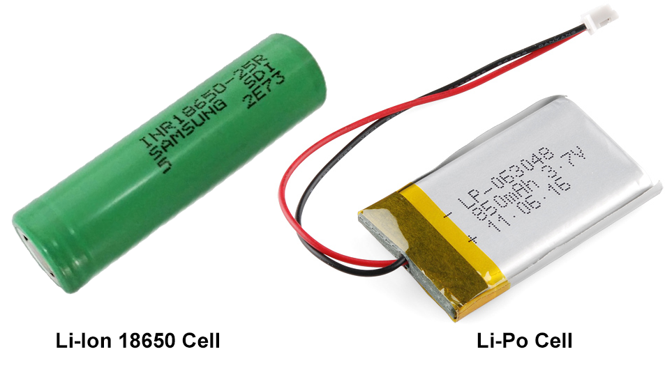
When it comes to lithium cells there are only two options to really consider, these are 18650 Li-Ion cells and flat packed Li-Po cells. While choosing cells, only cells from leading manufacturers (LG, Panasonic, Samsung, Sony, etc.) should be considered. These cells are better built and safer to use than Chinese counterfits. As well as the capacity of these cells are closer to what's advertised.
I specify 18650 Li-Ion cells over all the other standard sizes of Li-Ion cells for one simple reason, Tesla uses 18650 cells. While Tesla cells aren't widely available on the market, they are driving the competition to make higher capacity cells at a lower cost. Before Tesla's Gigafactory the average high capacity cell from the leading manufacturers was 2500mAh. Today the leading manufactures are starting to break the 3000mAh barrier. Panasonic has some that are labeled at 3400mAh but the actual capacity is lower (more on this later).
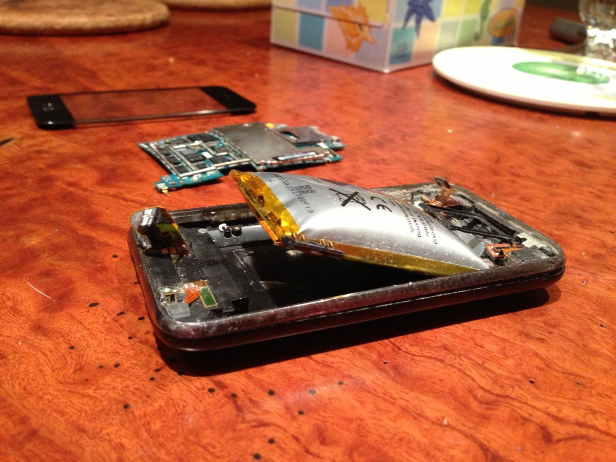
As for the Li-Po cells, there's more variety in the form factor so there isn't a recommended physical size. One thing to note about Li-Po flat pack cells is that they are very fragile. Excessive heat from improper charging and discharging can cause these cells to swell. Once these cells swell they are a ticking time bomb! The form factor also contributes to the fragility of this type of cell. They are soft and malleable when compared to the hard shell of an 18650 cell. This makes Li-Po cells prone to punctures from surrounding through-hole mounted components in a portable. If you puncture a cell it will go up in an inferno.
For a first time battery builder, I'd recommend the 18650 cells over the Li-Po cells for the sake of safety. Although the Li-Po cell's form factor will allow for a much thinner portable. Most quality 18650 cells have a safety fuse inside them that will pop when too much current is drawn from the cell or (more likely) when they get too hot while trying to solder to them. It's still possible to safely solder to an 18650 it just requires the area to be roughed up a little with sandpaper, some flux, and a lot of heat over a short period of time. It's easier to just use battery holders for 18650 cells because they are cheap and cells can be easily swapped out.
If Li-Po cells are chosen, then soldering directly to the cell is the only option. Try to find Li-Po cells with long wires already attached. Long wires will allow for more solder time because the heat will penetrate the cell slower. If the cell doesn't have attached wires then allow the cell to cool between soldering each contact. If you get a Li-Po too hot it will swell and should be discarded.
How Many Cells
Lithium cells have a nominal voltage of 3.6-3.7 volts while the operating voltage range is generally from 4.2 volts to 3.0 volts (although this can vary, some cells can happily discharge down to 2.5 volts so check the data sheet). Never ever use cells that have been outside the operating voltage. If a cell exceeds 4.2 volts it CAN and WILL blow up. If a cell goes below 3.0 volts the battery chemistry can be damaged causing reduced battery life, increased internal resistance, and an imbalance in the battery pack (more on this later).
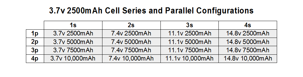
This operating voltage range must be taken in consideration while designing a battery. It's crucial to make sure the max charge voltage and max discharge voltage are within the acceptable range for the input voltage on the voltage regulators in your portable. The way to control the voltage of a battery is to change the number of cells in series. Conversely, the number of cells in parallel will change the capacity. The number of cells in series and parallel are denoted by “s” and “p” values when describing a battery. As well as the battery's voltage is described by the nominal voltage. Here's a table of basic battery configurations based off of a 3.7v 2500mAh cell. The “s” number and “p” number are multiplied to give you total number of cells. So a 2s1p 7.4v 2500mAh battery has 2 cells. And a 4s3p 14.8v 7500mAh battery has 12 cells. NOTE: A lithium battery requires a protection board so continue reading to that section before building a battery.
Discharging
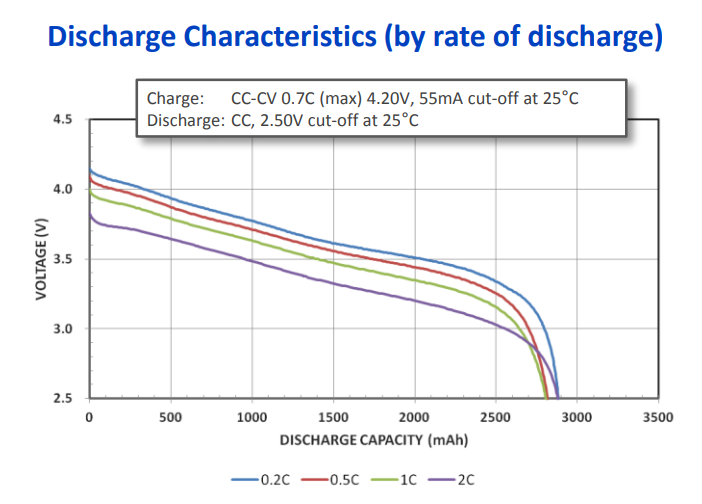
When a cell discharges, the voltage drops in a curve (see the graph below). This discharge characteristic can greatly reduce battery life in a portable that relies on low-dropout (LDO) regulators to make the required input voltage.
For example, a Nintendo 64 requires input voltages of 3.3 volts and 5 volts to operate. Most people use a TI 08080 switching regulator to get 3.3 volts, but rely on the built in LDO regulator to provide 5 volts. Depending on the N64's revision, the built in LDO regulator has a dropout voltage of 1.6-2.0 volts. So if a 2 cell 7.4 volt battery is being used, which operates from 8.4 volts to 6.0 volts, the bottom 30% of the battery's capacity cannot be used. Once the battery voltage drops below 7.0-6.6 volts the LDO stops making 5 volts.
The solution to this problem is to either build a better 5 volt regulator. Or to simply build a 3 cell 11.1 volt battery that operates from 12.6 volts down to 9.0 volts.
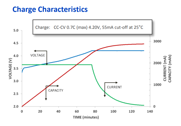
Charging
Lithium cells require a special kind of charging when compared to other battery chemistry types. This type of charging is often refered to as “Smart Charging” otherwise known as a Constant Current / Constant Voltage Charging (or a CC/CV Charging). The charge cycle starts with Constant Current while the voltage slowly ramps up. Once the cells reach around 70-80% capacity (around 4.1 volts) the charger goes into a Constant Voltage mode while the current tapers down (see the graph below).
C Rating
A specification that needs attention while building batteries is the “C” rating (Capacity Rating). It's basically the mAh rating of the battery converted to amps. In a 7.4v 2500mAh 2s1p battery 1C equals 2.5 amps. In a 7.4v 5000mAh 2s2p battery 1C equals 5 amps. Simple enough. The C rating is important because cells can generally only be discharged at 1-2C and charged at 0.5-1C (refer to the datasheet for your cells). So a 7.4v 2500mAh 2s1p battery can be safely discharged at 2.5 amps (1C) and it will last one hour. If it is discharged at 5 amps (2C) with will only last half an hour. If we wanted to charge this battery at 0.5C, then we would need a charger that can provide 1.25 amps which will take a little over two hours to charge. Or if we had a charger that could charge at 2.5 amps (1C) the battery will charge in a little over one hour.
When talking about discharging batteries, C ratings are more important when dealing with motors in R/C's and EV's. DC motors require a lot of amps and will over draw current from batteries. In our application it's not as much of an issue unless you are planning to run a power hungry console like an original PS3 (200ish watts) off batteries. Whereas the average Nintendo 64 portable draws around 12 watts. Which can be powered by a 7.4v 2500mAh 2s1p battery that can safely provide 18.5 watts of power continuously while being discharged at 1C (7.4v * 2.5Ah = 18.5w).
C rating is more important to portablizing when considering a charger. Try to find a charger that can charge at 0.5C to 1C of your battery. If your charger has a smaller charge current than 0.5C then it will take longer to charge your battery.
Internal Resistance
Another characteristic of building a battery is the internal resistance of the cells. Every cell has a certain amount of internal resistance. This internal resistance is what causes capacity variation from cell to cell from the same lot. Over many cycles the internal resistance increases causing reduced cell capacity and voltage drop. If a cell is allowed to operate outside the 4.2-3.0 volt range or draw more than 2C continuously, the lithium chemistry breaks down, increasing internal resistance. Increased internal resistance will also manifest itself in large batteries as voltage drop.
For example, I have 4 new 10s2p batteries that have a max voltage that varies from 40.5-41.5 volts from battery to battery. In a perfect world they would all have a max voltage of 42 volts. So don't be alarmed if you see a small voltage drop across your battery. In my 20 cell batteries there's a 0.025-0.075 volt drop per cell. This sort of a voltage drop is meaningless in our application of building portables but in the R/C and EV world it causes a decrease in the max RPM of motors.
Battery Life
Finally, the last thing to know about choosing cells is how to roughly calculate battery life. Basically, if a battery is discharged at 1C it will be fully discharged in 1 hour (and discharged at 2C in half an hour). If the nominal voltage is multiplied by the amp hours (not milliamps hours, mAh) you get watt hours. So a 7.4v 2500mAh 2s battery is 18.5 watt hours.
7.4v * 2.5Ah = 18.5wh
Now divide the watt hours of the battery pack by the power draw of the portable in watts. In the case of a basic Nintendo 64 portable that draws 12 watts you get 1.54h.
18.5wh / 12w = 1.54h
Wait, we aren't done yet. This is the theoretical battery life in a perfect world. It doesn't take into account the variable internal resistance of the cells or the energy lost to heat (cells get warm when they discharge). So to be on the safe side subtract 25% which gives an estimated battery life of 1.16 hours or about 70 minutes.
1.54h * .75 = 1.16h
Battery Protection Boards (PCB/PCM/BMS)
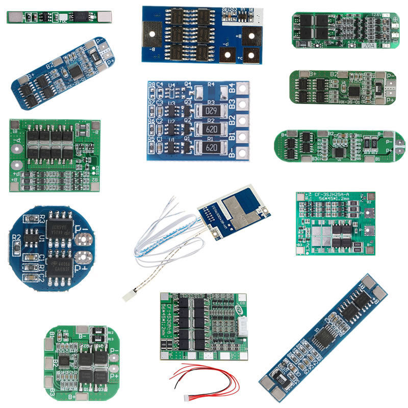
(Pictured)
http://www.ebay.com/itm/1S-2S-4S-3S...650-Li-ion-Lithium-Battery-Cell-/192217997007
When implementing lithium batteries you must ALWAYS use a protection board. There are basic protection boards and some that are more robust. These are usually listed with a variety of names which adds to the confusion. They can be called some of the following PCB, PCM, BMS, and/or CMB.
A PCB/PCM (Protection Circuit Board / Protection Circuit Module) is the simplest of the protection boards. These boards provide short circuit protection, over-current protection, over-volt protection, and under-volt protection. At the very least you must use one of these.
A BMS (Battery Management System) does everything a PCB/PCM can but with the added feature of balancing cells. The way a BMS balances cells is to provide resistance to individual cells to slightly discharge them when they exceed 4.20 volts. For our purposes I will be referring to any PCB/PCM/BMS that has individual connections to each cell as a BMS. Using a BMS is much safer then a PCB/PCM with no drawbacks.
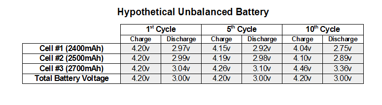
The primary reason to use a BMS over a PCB/PCM is cells in a battery can get imbalanced over time. It's important to use matched cells to combat this. However, cells with the same part number can slightly vary in capacity from cell to cell. In the table below I've made a hypothetical scenario of what can happen over time with an unbalanced pack without a BMS. As you can see the more cycles the more out of balance the cells get. The real danger is that with these cells in series the voltage always adds up to safe levels. So the PCB/PCM will never trip the over-voltage or under-voltage protection. While the Cell #3 is continually getting over-charged (risking explosion) and Cell's #1 and #2 are getting over-discharged. The more a cell goes below 3.0v the more damage to the lithium chemistry. This damage reduces capacity thus further imbalancing the battery pack.
NOTE: After cells are connected to a protection board, it's common for these protection boards to behave erratically until a charge current is applied to the Charge Terminal on the board. This is because the board needs to be turned on in a sense. The behavior that is common is either no voltage on the Output Terminal or the voltage drops to zero the moment you try to draw from the Output Terminal.
If it's not labeled, a good rule of thumb is that on a PCB/PCM or a BMS the Charge Terminal and the Output terminal are shared. However, on a CMB (see below) it's a feature to have separate Charge and Output Terminals.
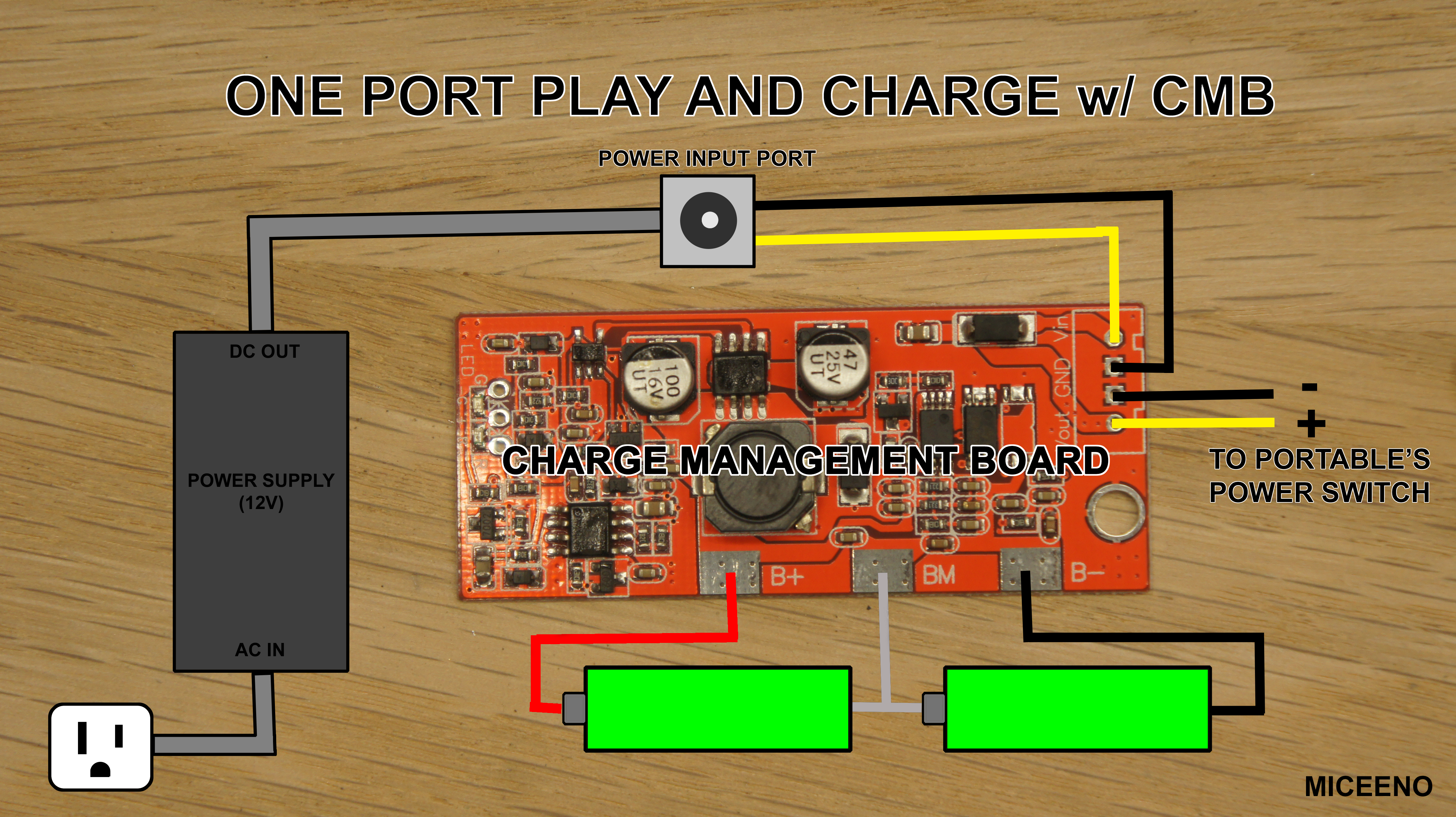
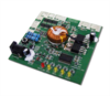
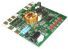
Charge Management Boards (1 Port Play and Charge)
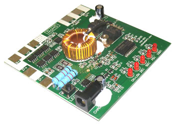
A CMB (Charge Management Board) is a BMS with an integrated charger. This type of board is the holy grail for our purposes. You can identify a CMB from a BMS by the coil on the board and the separate voltage in (Vin) and voltage out (Vout) terminals. A properly engineered CMB will allow for a “1 port play and charge” right out of the box. It's uses a MOSFET to automatically disconnect the battery from the output while charging and provide power from the external power supply to the output instead. Then when the external power is removed the MOSFET automatically reconnects the battery back to the output. For our purposes I recommend to just use one of these. The only problem is they are fairly hard to find. I will include a section at the end of known good boards to use.
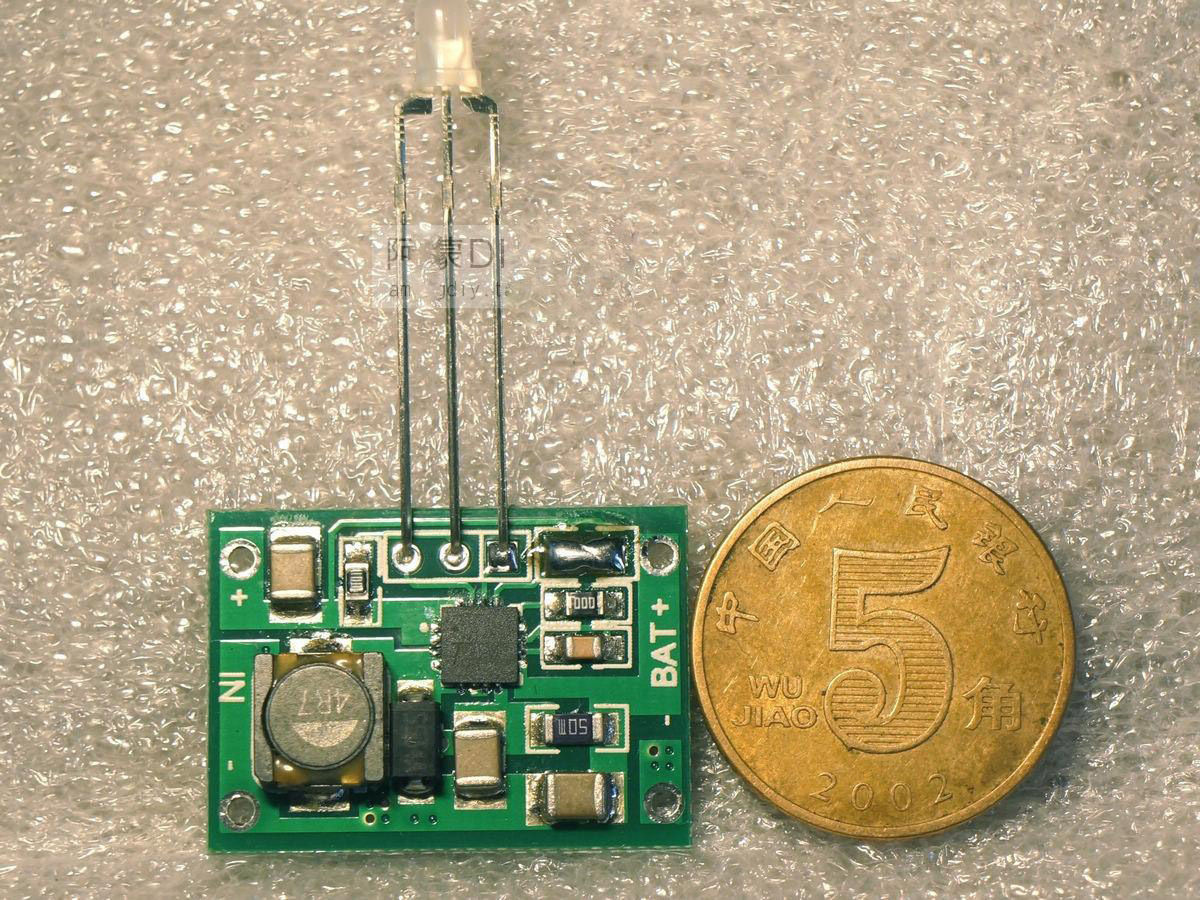
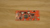
Stand Alone Charge Boards (1 Port Play and Charge)
(Pictured)
http://www.ebay.com/itm/2Cells-Sing...le-1-2A-PCB-18650-TP5100-Iphone-/201849640517
The final board to talk about is a stand alone charge board. This is a charger that doesn't have a built in BMS. To safely use one of these you will NEED a PCB/PCM or a BMS to protect your cells and this circuit (pictured below) that I've come up with for a “1 port play and charge” system. This circuit works exactly how the CMB boards work.
The reason one would use a stand alone charge board over an all in one CMB is that CMB's are fairly hard to find. The other advantage is that there are more options for stand alone charge board's with increased charge current for faster battery charging.
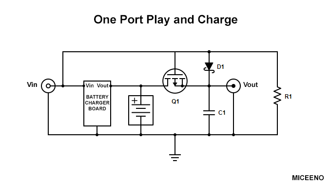
This circuit relies on a P Channel MOSFET. When the Gate is pulled to ground with the pull-down resistor the MOSFET acts like a closed switch between the Drain and Source. It is in this state when the portable is operating off of battery power. The Schottky diode keeps the power from the battery from going back around to the charger board. Schottky diode's tend to leak a little so the pull-down resistor also has to be adequate enough to handle the leakage.
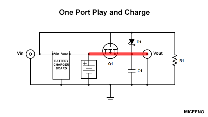
When the Gate is pulled high by the external power supply from Vin the MOSFET acts like an open switch between Drain and Source. This will disconnect the battery from the portable, allowing it to charge safely and properly, while providing power to the portable from Vin through the Schottky diode. The MOSFET and Schottky diode switch very quickly but a Capacitor is added to smooth the transition.
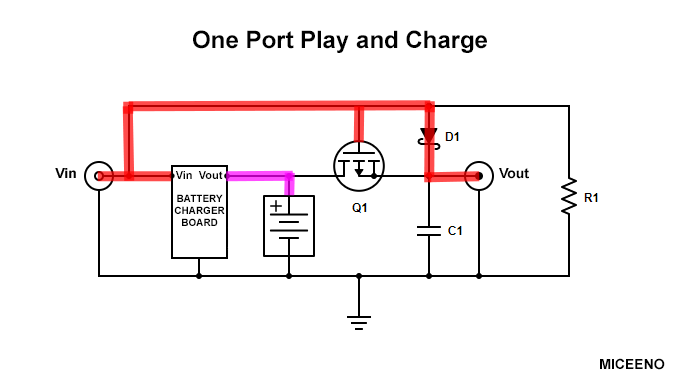
I don't have the values of Q1, D1, R1, and C1 listed because I'm waiting on a P Channel MOSFET to arrive to fully test and optimize this circuit. The primary concerns are to do with battery life. When a P Channel MOSFET is acting like a closed switch, there is a small amount of resistance between Drain and Source. This resistance causes heat and power draw. The other component to be concerned with is the Schottky diode. The leak back current will also effect battery life. The test parts I purchased aren't the ones in my final design (which I will post in it's own thread or update here). They are ones that I can get the quickest. The test MOSFET has an Rds(ON) resistance of 0.2 Ohms and the test Schottky diode has a leak current of .002 Amps. The CMBs have a listed below have an Rds(ON) Resistance around 0.050 Ohms, so this is the target in my final design.
Recommended 2s CMBs
http://www.ebay.com/itm/Intelligent...2S-Packs-18650-lithium-Satellite/311721987212
Price: ~$8 Shipped
Model: CX-74-2S (V1.0)
Size: 62x26x6.9mm
Input Charging Voltage: 9-15v
Charging Voltage: 8.40-8.45v
Charging Current: 1A
Over-Discharge Protection Voltage Range: 4.6-5.1v
Short Circuit Protection: Yes
Maximum Operating Current: 2-3A
Disconnects Battery While Charging: Yes
MOSFET Drain-Source Resistance: 0.045 Ohm
Integrated Fuel Gauge: No
Recommended 3s CMBs
http://www.batteryspace.com/CMB-for-11.1V-Li-Ion-Battery-Pack-10A-limit-RoHS-Compliant-with-DC-char.aspx
Datasheet:
http://www.batteryspace.com/prod-specs/4889-CMB-S3A3.pdf
Price: $43.95
Model: CMB-S3A3
Size: 82x82x20mm
Input Charging Voltage: 14-22v
Charging Voltage: 12.6v
Charging Current: 3A
Over-Discharge Protection Voltage: 7.2-9v
Short Circuit Protection: Yes
Maximum Operating Current: 10A
Disconnects Battery While Charging: Yes
MOSFET Drain-Source Resistance: <.050 Ohm
Integrated Fuel Gauge: Yes
Recommended 4s CMBs
http://www.batteryspace.com/CMB-for...ck-10A-limit-RoHS-Compliant-with-DC-char.aspx
Datasheet:
http://www.batteryspace.com/prod-specs/4888-CMB-S4A3.pdf
Price: $49.95
Model: CMB-S4A3
Size: 82x82x20mm
Input Charging Voltage: 18-24v
Charging Voltage: 16.8v
Charging Current: 3A
Over-Discharge Protection Voltage: 9.6-12v
Short Circuit Protection: Yes
Maximum Operating Current: 10A
Disconnects Battery While Charging: Yes
MOSFET Drain-Source Resistance: <.050 Ohm
Integrated Fuel Gauge: Yes
Testing Actual Battery Capacity
The final topic of this thread, which possibly deserves its own thread if enough people get on board, is how to test actual battery capacity. All manufacturers seem to overrate the capacity of their cells. The Chinese fakes are the worst for this.
My testing methodology is what is generally accepted in the E-Bike and EV communities. Which is to use this inexpensive LiPro Balance Charger / Discharger:
http://www.ebay.com/itm/Imax-B6-LCD-Screen-RC-Lipo-NiMh-Li-io-n-LiFe-Battery-LiPro-Balance-Charger/350782413357
First charge all the cells at 0.5C-1C. In the case of unknown C rates I usually charge at .5C of what is printed on the cells. Charge the cells individually to max capacity (4.2v). Then discharge individually at 1 amp until empty (3.0v). Record the measured mAh.
Here is a video of a guy testing random cells to show you how the tool works:
https://www.youtube.com/watch?v=xREp4T2hKIM
Tested Cells
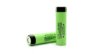
Panasonic 3400mah NCR18650B MH12210 (Green)
Plausible Datasheets:
https://na.industrial.panasonic.com/sites/default/pidsa/files/ncr18650b.pdf
https://engineering.tamu.edu/media/4247819/ds-battery-panasonic-18650ncr.pdf
Cell 1 - 2887mah
Cell 2 - 2932mah
Cell 3 - 2887mah
Cell 4 - 2933mah
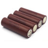
LG 3000mah HG2 High Drain LGDBHG21865 (Brown)
Plausible Datasheet:
https://www.nkon.nl/sk/k/hg2.pdf
Cell 1 - 2544mah
Cell 2 - 2556mah
Cell 3 - 2532mah
Cell 4 - 2543mah

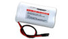
LGEAMF11865 LG ICR18650 MF1 2150mAh
Plausible Datasheet:
https://www.imrbatteries.com/content/lg_MF1.pdf
Cell 1/2 - 2229mAh**
Cell 3/4 - 2203mAh**
Cell 5/6 - 2217mAh**
Cell 7/8 - 2241mAh**
Cell 9/10 - 2237mAh**
Cell 11/12 - 2243mAh**
Cell 13/14 - 2242mAh**
Cell 15/16 - 2257mAh**
Cell 17/18 - 2238mAh**
Cell 19/20 - 2226mAh**
Tenergy 2200mAh
Plausible Datasheet:
http://www.tenergy.com/core/media/media.nl/id.36145/c.671216/.f?h=384b24cc1d4ad2a6829c
Cell 1/2 – 1966mAh

Ultrafire BRC 18650 3000mah
Cell 1 - 862mAh
Cell 2 - 931mAh
Credits
This guide, including all tables and diagrams, are provided courtesy of @Miceeno.
Li-Ion vs. Li-Po
When it comes to lithium cells there are only two options to really consider, these are 18650 Li-Ion cells and flat packed Li-Po cells. While choosing cells, only cells from leading manufacturers (LG, Panasonic, Samsung, Sony, etc.) should be considered. These cells are better built and safer to use than Chinese counterfits. As well as the capacity of these cells are closer to what's advertised.
I specify 18650 Li-Ion cells over all the other standard sizes of Li-Ion cells for one simple reason, Tesla uses 18650 cells. While Tesla cells aren't widely available on the market, they are driving the competition to make higher capacity cells at a lower cost. Before Tesla's Gigafactory the average high capacity cell from the leading manufacturers was 2500mAh. Today the leading manufactures are starting to break the 3000mAh barrier. Panasonic has some that are labeled at 3400mAh but the actual capacity is lower (more on this later).
As for the Li-Po cells, there's more variety in the form factor so there isn't a recommended physical size. One thing to note about Li-Po flat pack cells is that they are very fragile. Excessive heat from improper charging and discharging can cause these cells to swell. Once these cells swell they are a ticking time bomb! The form factor also contributes to the fragility of this type of cell. They are soft and malleable when compared to the hard shell of an 18650 cell. This makes Li-Po cells prone to punctures from surrounding through-hole mounted components in a portable. If you puncture a cell it will go up in an inferno.
For a first time battery builder, I'd recommend the 18650 cells over the Li-Po cells for the sake of safety. Although the Li-Po cell's form factor will allow for a much thinner portable. Most quality 18650 cells have a safety fuse inside them that will pop when too much current is drawn from the cell or (more likely) when they get too hot while trying to solder to them. It's still possible to safely solder to an 18650 it just requires the area to be roughed up a little with sandpaper, some flux, and a lot of heat over a short period of time. It's easier to just use battery holders for 18650 cells because they are cheap and cells can be easily swapped out.
If Li-Po cells are chosen, then soldering directly to the cell is the only option. Try to find Li-Po cells with long wires already attached. Long wires will allow for more solder time because the heat will penetrate the cell slower. If the cell doesn't have attached wires then allow the cell to cool between soldering each contact. If you get a Li-Po too hot it will swell and should be discarded.
How Many Cells
Lithium cells have a nominal voltage of 3.6-3.7 volts while the operating voltage range is generally from 4.2 volts to 3.0 volts (although this can vary, some cells can happily discharge down to 2.5 volts so check the data sheet). Never ever use cells that have been outside the operating voltage. If a cell exceeds 4.2 volts it CAN and WILL blow up. If a cell goes below 3.0 volts the battery chemistry can be damaged causing reduced battery life, increased internal resistance, and an imbalance in the battery pack (more on this later).
This operating voltage range must be taken in consideration while designing a battery. It's crucial to make sure the max charge voltage and max discharge voltage are within the acceptable range for the input voltage on the voltage regulators in your portable. The way to control the voltage of a battery is to change the number of cells in series. Conversely, the number of cells in parallel will change the capacity. The number of cells in series and parallel are denoted by “s” and “p” values when describing a battery. As well as the battery's voltage is described by the nominal voltage. Here's a table of basic battery configurations based off of a 3.7v 2500mAh cell. The “s” number and “p” number are multiplied to give you total number of cells. So a 2s1p 7.4v 2500mAh battery has 2 cells. And a 4s3p 14.8v 7500mAh battery has 12 cells. NOTE: A lithium battery requires a protection board so continue reading to that section before building a battery.
Discharging
When a cell discharges, the voltage drops in a curve (see the graph below). This discharge characteristic can greatly reduce battery life in a portable that relies on low-dropout (LDO) regulators to make the required input voltage.
For example, a Nintendo 64 requires input voltages of 3.3 volts and 5 volts to operate. Most people use a TI 08080 switching regulator to get 3.3 volts, but rely on the built in LDO regulator to provide 5 volts. Depending on the N64's revision, the built in LDO regulator has a dropout voltage of 1.6-2.0 volts. So if a 2 cell 7.4 volt battery is being used, which operates from 8.4 volts to 6.0 volts, the bottom 30% of the battery's capacity cannot be used. Once the battery voltage drops below 7.0-6.6 volts the LDO stops making 5 volts.
The solution to this problem is to either build a better 5 volt regulator. Or to simply build a 3 cell 11.1 volt battery that operates from 12.6 volts down to 9.0 volts.
Charging
Lithium cells require a special kind of charging when compared to other battery chemistry types. This type of charging is often refered to as “Smart Charging” otherwise known as a Constant Current / Constant Voltage Charging (or a CC/CV Charging). The charge cycle starts with Constant Current while the voltage slowly ramps up. Once the cells reach around 70-80% capacity (around 4.1 volts) the charger goes into a Constant Voltage mode while the current tapers down (see the graph below).
C Rating
A specification that needs attention while building batteries is the “C” rating (Capacity Rating). It's basically the mAh rating of the battery converted to amps. In a 7.4v 2500mAh 2s1p battery 1C equals 2.5 amps. In a 7.4v 5000mAh 2s2p battery 1C equals 5 amps. Simple enough. The C rating is important because cells can generally only be discharged at 1-2C and charged at 0.5-1C (refer to the datasheet for your cells). So a 7.4v 2500mAh 2s1p battery can be safely discharged at 2.5 amps (1C) and it will last one hour. If it is discharged at 5 amps (2C) with will only last half an hour. If we wanted to charge this battery at 0.5C, then we would need a charger that can provide 1.25 amps which will take a little over two hours to charge. Or if we had a charger that could charge at 2.5 amps (1C) the battery will charge in a little over one hour.
When talking about discharging batteries, C ratings are more important when dealing with motors in R/C's and EV's. DC motors require a lot of amps and will over draw current from batteries. In our application it's not as much of an issue unless you are planning to run a power hungry console like an original PS3 (200ish watts) off batteries. Whereas the average Nintendo 64 portable draws around 12 watts. Which can be powered by a 7.4v 2500mAh 2s1p battery that can safely provide 18.5 watts of power continuously while being discharged at 1C (7.4v * 2.5Ah = 18.5w).
C rating is more important to portablizing when considering a charger. Try to find a charger that can charge at 0.5C to 1C of your battery. If your charger has a smaller charge current than 0.5C then it will take longer to charge your battery.
Internal Resistance
Another characteristic of building a battery is the internal resistance of the cells. Every cell has a certain amount of internal resistance. This internal resistance is what causes capacity variation from cell to cell from the same lot. Over many cycles the internal resistance increases causing reduced cell capacity and voltage drop. If a cell is allowed to operate outside the 4.2-3.0 volt range or draw more than 2C continuously, the lithium chemistry breaks down, increasing internal resistance. Increased internal resistance will also manifest itself in large batteries as voltage drop.
For example, I have 4 new 10s2p batteries that have a max voltage that varies from 40.5-41.5 volts from battery to battery. In a perfect world they would all have a max voltage of 42 volts. So don't be alarmed if you see a small voltage drop across your battery. In my 20 cell batteries there's a 0.025-0.075 volt drop per cell. This sort of a voltage drop is meaningless in our application of building portables but in the R/C and EV world it causes a decrease in the max RPM of motors.
Battery Life
Finally, the last thing to know about choosing cells is how to roughly calculate battery life. Basically, if a battery is discharged at 1C it will be fully discharged in 1 hour (and discharged at 2C in half an hour). If the nominal voltage is multiplied by the amp hours (not milliamps hours, mAh) you get watt hours. So a 7.4v 2500mAh 2s battery is 18.5 watt hours.
7.4v * 2.5Ah = 18.5wh
Now divide the watt hours of the battery pack by the power draw of the portable in watts. In the case of a basic Nintendo 64 portable that draws 12 watts you get 1.54h.
18.5wh / 12w = 1.54h
Wait, we aren't done yet. This is the theoretical battery life in a perfect world. It doesn't take into account the variable internal resistance of the cells or the energy lost to heat (cells get warm when they discharge). So to be on the safe side subtract 25% which gives an estimated battery life of 1.16 hours or about 70 minutes.
1.54h * .75 = 1.16h
Battery Protection Boards (PCB/PCM/BMS)
(Pictured)
http://www.ebay.com/itm/1S-2S-4S-3S...650-Li-ion-Lithium-Battery-Cell-/192217997007
When implementing lithium batteries you must ALWAYS use a protection board. There are basic protection boards and some that are more robust. These are usually listed with a variety of names which adds to the confusion. They can be called some of the following PCB, PCM, BMS, and/or CMB.
A PCB/PCM (Protection Circuit Board / Protection Circuit Module) is the simplest of the protection boards. These boards provide short circuit protection, over-current protection, over-volt protection, and under-volt protection. At the very least you must use one of these.
A BMS (Battery Management System) does everything a PCB/PCM can but with the added feature of balancing cells. The way a BMS balances cells is to provide resistance to individual cells to slightly discharge them when they exceed 4.20 volts. For our purposes I will be referring to any PCB/PCM/BMS that has individual connections to each cell as a BMS. Using a BMS is much safer then a PCB/PCM with no drawbacks.
The primary reason to use a BMS over a PCB/PCM is cells in a battery can get imbalanced over time. It's important to use matched cells to combat this. However, cells with the same part number can slightly vary in capacity from cell to cell. In the table below I've made a hypothetical scenario of what can happen over time with an unbalanced pack without a BMS. As you can see the more cycles the more out of balance the cells get. The real danger is that with these cells in series the voltage always adds up to safe levels. So the PCB/PCM will never trip the over-voltage or under-voltage protection. While the Cell #3 is continually getting over-charged (risking explosion) and Cell's #1 and #2 are getting over-discharged. The more a cell goes below 3.0v the more damage to the lithium chemistry. This damage reduces capacity thus further imbalancing the battery pack.
NOTE: After cells are connected to a protection board, it's common for these protection boards to behave erratically until a charge current is applied to the Charge Terminal on the board. This is because the board needs to be turned on in a sense. The behavior that is common is either no voltage on the Output Terminal or the voltage drops to zero the moment you try to draw from the Output Terminal.
If it's not labeled, a good rule of thumb is that on a PCB/PCM or a BMS the Charge Terminal and the Output terminal are shared. However, on a CMB (see below) it's a feature to have separate Charge and Output Terminals.
Charge Management Boards (1 Port Play and Charge)
A CMB (Charge Management Board) is a BMS with an integrated charger. This type of board is the holy grail for our purposes. You can identify a CMB from a BMS by the coil on the board and the separate voltage in (Vin) and voltage out (Vout) terminals. A properly engineered CMB will allow for a “1 port play and charge” right out of the box. It's uses a MOSFET to automatically disconnect the battery from the output while charging and provide power from the external power supply to the output instead. Then when the external power is removed the MOSFET automatically reconnects the battery back to the output. For our purposes I recommend to just use one of these. The only problem is they are fairly hard to find. I will include a section at the end of known good boards to use.
Stand Alone Charge Boards (1 Port Play and Charge)
(Pictured)
http://www.ebay.com/itm/2Cells-Sing...le-1-2A-PCB-18650-TP5100-Iphone-/201849640517
The final board to talk about is a stand alone charge board. This is a charger that doesn't have a built in BMS. To safely use one of these you will NEED a PCB/PCM or a BMS to protect your cells and this circuit (pictured below) that I've come up with for a “1 port play and charge” system. This circuit works exactly how the CMB boards work.
The reason one would use a stand alone charge board over an all in one CMB is that CMB's are fairly hard to find. The other advantage is that there are more options for stand alone charge board's with increased charge current for faster battery charging.
This circuit relies on a P Channel MOSFET. When the Gate is pulled to ground with the pull-down resistor the MOSFET acts like a closed switch between the Drain and Source. It is in this state when the portable is operating off of battery power. The Schottky diode keeps the power from the battery from going back around to the charger board. Schottky diode's tend to leak a little so the pull-down resistor also has to be adequate enough to handle the leakage.
When the Gate is pulled high by the external power supply from Vin the MOSFET acts like an open switch between Drain and Source. This will disconnect the battery from the portable, allowing it to charge safely and properly, while providing power to the portable from Vin through the Schottky diode. The MOSFET and Schottky diode switch very quickly but a Capacitor is added to smooth the transition.
I don't have the values of Q1, D1, R1, and C1 listed because I'm waiting on a P Channel MOSFET to arrive to fully test and optimize this circuit. The primary concerns are to do with battery life. When a P Channel MOSFET is acting like a closed switch, there is a small amount of resistance between Drain and Source. This resistance causes heat and power draw. The other component to be concerned with is the Schottky diode. The leak back current will also effect battery life. The test parts I purchased aren't the ones in my final design (which I will post in it's own thread or update here). They are ones that I can get the quickest. The test MOSFET has an Rds(ON) resistance of 0.2 Ohms and the test Schottky diode has a leak current of .002 Amps. The CMBs have a listed below have an Rds(ON) Resistance around 0.050 Ohms, so this is the target in my final design.
Recommended 2s CMBs
http://www.ebay.com/itm/Intelligent...2S-Packs-18650-lithium-Satellite/311721987212
Price: ~$8 Shipped
Model: CX-74-2S (V1.0)
Size: 62x26x6.9mm
Input Charging Voltage: 9-15v
Charging Voltage: 8.40-8.45v
Charging Current: 1A
Over-Discharge Protection Voltage Range: 4.6-5.1v
Short Circuit Protection: Yes
Maximum Operating Current: 2-3A
Disconnects Battery While Charging: Yes
MOSFET Drain-Source Resistance: 0.045 Ohm
Integrated Fuel Gauge: No
Recommended 3s CMBs
http://www.batteryspace.com/CMB-for-11.1V-Li-Ion-Battery-Pack-10A-limit-RoHS-Compliant-with-DC-char.aspx
Datasheet:
http://www.batteryspace.com/prod-specs/4889-CMB-S3A3.pdf
Price: $43.95
Model: CMB-S3A3
Size: 82x82x20mm
Input Charging Voltage: 14-22v
Charging Voltage: 12.6v
Charging Current: 3A
Over-Discharge Protection Voltage: 7.2-9v
Short Circuit Protection: Yes
Maximum Operating Current: 10A
Disconnects Battery While Charging: Yes
MOSFET Drain-Source Resistance: <.050 Ohm
Integrated Fuel Gauge: Yes
Recommended 4s CMBs
http://www.batteryspace.com/CMB-for...ck-10A-limit-RoHS-Compliant-with-DC-char.aspx
Datasheet:
http://www.batteryspace.com/prod-specs/4888-CMB-S4A3.pdf
Price: $49.95
Model: CMB-S4A3
Size: 82x82x20mm
Input Charging Voltage: 18-24v
Charging Voltage: 16.8v
Charging Current: 3A
Over-Discharge Protection Voltage: 9.6-12v
Short Circuit Protection: Yes
Maximum Operating Current: 10A
Disconnects Battery While Charging: Yes
MOSFET Drain-Source Resistance: <.050 Ohm
Integrated Fuel Gauge: Yes
Testing Actual Battery Capacity
The final topic of this thread, which possibly deserves its own thread if enough people get on board, is how to test actual battery capacity. All manufacturers seem to overrate the capacity of their cells. The Chinese fakes are the worst for this.
My testing methodology is what is generally accepted in the E-Bike and EV communities. Which is to use this inexpensive LiPro Balance Charger / Discharger:
http://www.ebay.com/itm/Imax-B6-LCD-Screen-RC-Lipo-NiMh-Li-io-n-LiFe-Battery-LiPro-Balance-Charger/350782413357
First charge all the cells at 0.5C-1C. In the case of unknown C rates I usually charge at .5C of what is printed on the cells. Charge the cells individually to max capacity (4.2v). Then discharge individually at 1 amp until empty (3.0v). Record the measured mAh.
Here is a video of a guy testing random cells to show you how the tool works:
https://www.youtube.com/watch?v=xREp4T2hKIM
Tested Cells
Panasonic 3400mah NCR18650B MH12210 (Green)
Plausible Datasheets:
https://na.industrial.panasonic.com/sites/default/pidsa/files/ncr18650b.pdf
https://engineering.tamu.edu/media/4247819/ds-battery-panasonic-18650ncr.pdf
Cell 1 - 2887mah
Cell 2 - 2932mah
Cell 3 - 2887mah
Cell 4 - 2933mah
It appears there are two very similar datasheets for this cell. The part numbers only differ by a "B" at the end. According to the datasheets the "B" cells have more capacity. So look for the "B" in the part number when purchasing these cells.
LG 3000mah HG2 High Drain LGDBHG21865 (Brown)
Plausible Datasheet:
https://www.nkon.nl/sk/k/hg2.pdf
Cell 1 - 2544mah
Cell 2 - 2556mah
Cell 3 - 2532mah
Cell 4 - 2543mah
LGEAMF11865 LG ICR18650 MF1 2150mAh
Plausible Datasheet:
https://www.imrbatteries.com/content/lg_MF1.pdf
Cell 1/2 - 2229mAh**
Cell 3/4 - 2203mAh**
Cell 5/6 - 2217mAh**
Cell 7/8 - 2241mAh**
Cell 9/10 - 2237mAh**
Cell 11/12 - 2243mAh**
Cell 13/14 - 2242mAh**
Cell 15/16 - 2257mAh**
Cell 17/18 - 2238mAh**
Cell 19/20 - 2226mAh**
I'm including these cells because they are an amazing deal. This eBay seller (alarmhookup) is unloading overstock from the hoverboard fad. The listings are for genuine LG and Samsung cells at $1.75 per cell. There are higher capacity cells that better suit our application of portablizing but these cells great for projects that require a lot of cells. I've personally got 4 of these 10s2p packs (80 cells) in my lawn mower and couldn't be happier with them.
http://www.ebay.com/itm/NEW-LG-36V-4-4AH-BATTERY-PACK-18650-EBIKE-VAPE-POWERWALL-BATTERIES-20-CELLS-BMS-/172630688902
http://www.ebay.com/itm/NEW-SAMSUNG...POWERWALL-BATTERIES-20-CELLS-BMS/201895735309
**Note: I didn't personally test these cells but there's a lot of people who already have. Here's a thorough review of these battery packs from eBay. I'm using the values from this video even though he discharges them down to 2.75 volts. The data sheet for these cells says this is safe to do so.
Tenergy 2200mAh
Plausible Datasheet:
http://www.tenergy.com/core/media/media.nl/id.36145/c.671216/.f?h=384b24cc1d4ad2a6829c
Cell 1/2 – 1966mAh
Ultrafire BRC 18650 3000mah
Cell 1 - 862mAh
Cell 2 - 931mAh
Credits
This guide, including all tables and diagrams, are provided courtesy of @Miceeno.